
Motion vector detection apparatus, method of detecting motion vectors, and image display device

Inactive Publication Date: 2009-03-05
HITACHI LTD
View PDF6 Cites 14 Cited by
  • Summary
  • Abstract
  • Description
  • Claims
  • Application Information

AI Technical Summary

Benefits of technology

[0010]Accordingly, it is an object of the present invention to provide a technique enabling accurate motion vectors to be detected even from edge regions in a frame of image where inaccurate motion vectors would normally tend to be detected in a case where motion vectors are detected from between a frame of image displayed in the past and the presently displayed frame of image.
[0019]In a yet additional embodiment, there are further provided a first low-pass filter connected between the input side of the motion vector-detecting unit and an image signal input unit enabling the image signal from the outside to be entered to remove High frequency components included in the image signal, a first information-reducing unit acting to reduce the amount of information of the image signal outputted from the first low-pass filter, and a fourth image signal delaying and outputting unit acting to output the image signal with a delay of a period of one frame with respect to the entered image signal by holding the image signal outputted from the first information-reducing unit.
[0021]In an additional embodiment, there are provided a second low-pass filter connected between the output side of the third image signal delaying and outputting unit and the input side of the second image signal delaying and outputting unit to remove RF components included in the image signal and a second information-reducing unit acting to reduce the amount of information of the image signal outputted from the second low-pass filter.
[0026]According to the present invention, in a case where motion vectors are detected between two frames of image which are successive in time, accurate motion vectors can be detected even from edge regions of a frame of image where inaccurate motion vectors would normally tend to be detected.

Problems solved by technology

However, where the above-described technique is adopted, it cannot be always said that motion vectors determined based on information about motion vectors in past frames of image are effectively used as motion vectors in the presently noticed frame.
Therefore, in the technique disclosed in the above-cited patent reference 1 (JP-A-2005-287048), it is difficult to detect accurate motion vectors at edge regions of the frame of image where inaccurate motion vectors tend to be detected.

Method used


Image

  • Motion vector detection apparatus, method of detecting motion vectors, and image display device
  • Motion vector detection apparatus, method of detecting motion vectors, and image display device
  • Motion vector detection apparatus, method of detecting motion vectors, and image display device

Examples


Embodiment Construction

[0038]Embodiments of the present invention are hereinafter described in further detail with reference to the drawings.

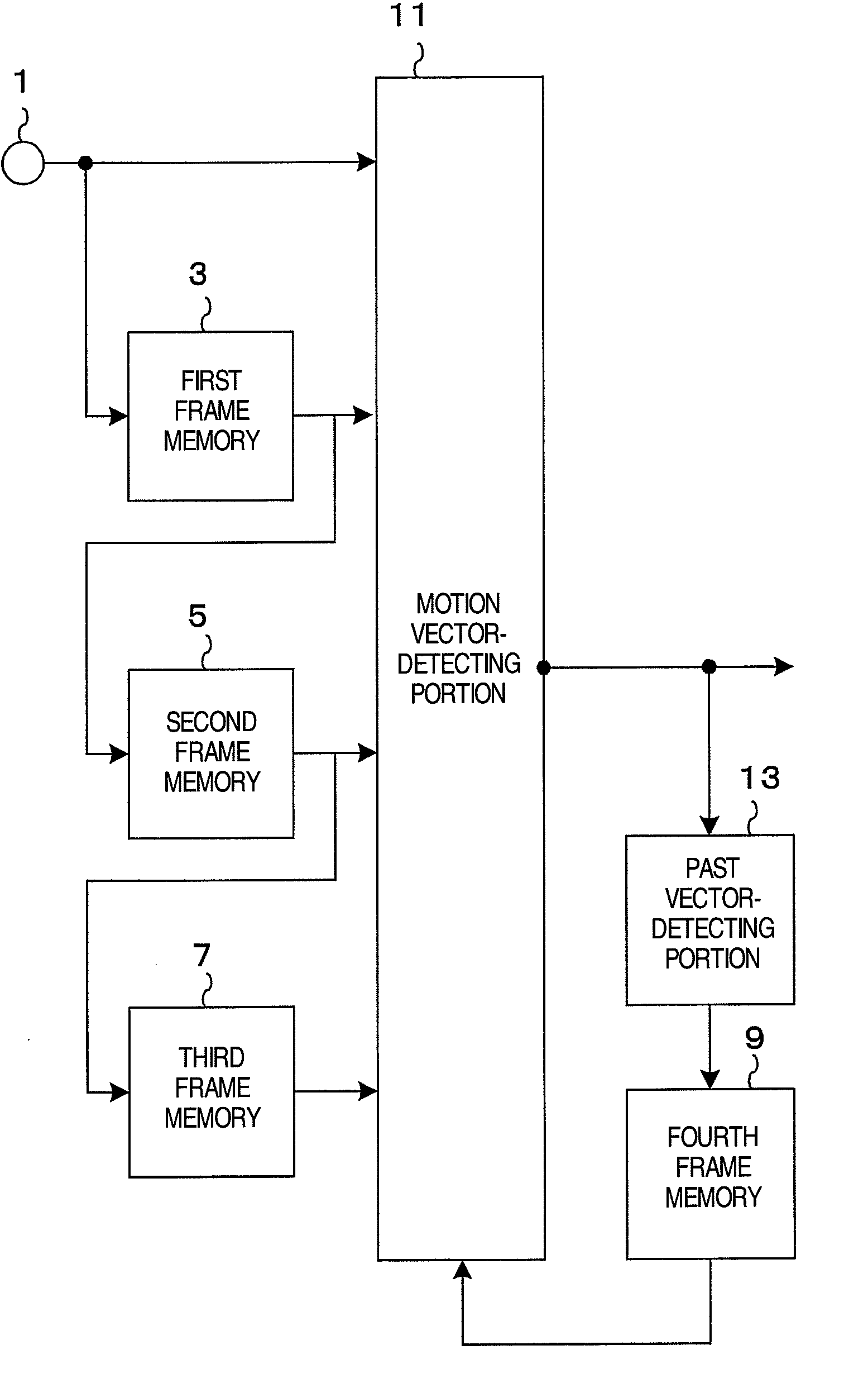
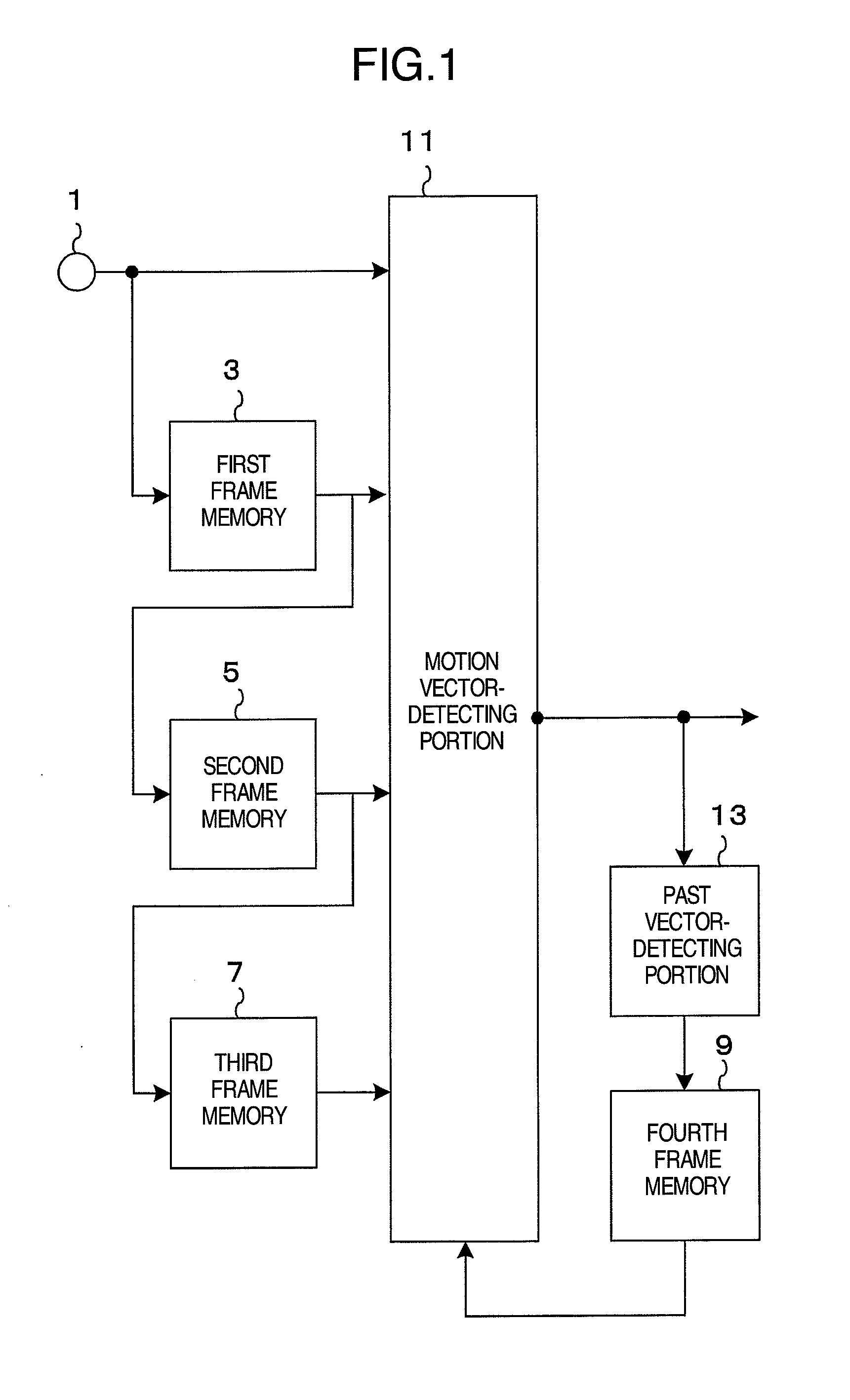
[0039]FIG. 1 is a block diagram showing the whole configuration of a motion vector detection apparatus associated with one embodiment of the present invention. The motion vector detection apparatus is built, for example, in an image display device such as a digital TV receiver.

[0040]The motion vector detection apparatus is designed to perform given signal processing while receiving an image signal as its input signal, the signal being exclusively in a digital format. Therefore, where an image signal in an analog format is supplied as the input signal to the image display device, the image signal is converted into a digital format by an analog-to-digital converter portion equipped in the image display device and then entered into the motion vector detection apparatus. As shown in FIG. 1, the motion vector detection apparatus has a signal input portion 1, plural frame ...


PUM


Abstract

A motion vector detection apparatus is disclosed capable of detecting accurate motion vectors from between a previous frame of image and the presently displayed frame of image even in edge regions of the frames where inaccurate motion vectors would normally tend to be detected. A motion vector-detecting portion reads in an image signal from the signal input portion as well as image signals entered through first through third frame memories. Processing for detecting motion vectors is performed, based on four frames entered in synchronism to the motion vector-detecting portion out of the frames forming the image signals. Vectors produced between the image signal from the first frame memory delayed by one frame relative to the image signal from the signal input portion and the image signal from the second frame memory delayed by two frames relative to the image signal from the signal input portion are detected as motion vectors.

Description

INCORPORATION BY REFERENCE[0001]The present application claims priority from Japanese application JP2007-016311 filed on Jan. 26, 2007, the content of which is hereby incorporated by reference into this application.BACKGROUND OF THE INVENTION[0002]The present invention relates to a motion vector detection apparatus for finding motion vectors from an image signal in a digital format. The invention also relates to a method of detecting motion vectors and to an image display device equipped with such a motion vector detection apparatus.[0003]A motion vector is a vector connecting pixels which show the best match when a preceding frame of image (image displayed in the past) is matched to the presently displayed frame of image. The matching is performed within a given search area to determine motion vectors. In other words, a motion vector technique is a method of expressing data about a motion picture sequence. In particular, a reference frame (i.e., a frame of image occurring at some i...

Claims


Application Information

Patent Timeline
IPC IPC(8): H04N7/01H04N5/14
CPCH04N7/012H04N7/014H04N7/0127
Inventor TAKANOHASHI, KENTAOGINO, MASAHIROMIZUHASHI, YOSHIAKI
Owner HITACHI LTD
Features
  • Generate Ideas
  • Intellectual Property
  • Life Sciences
  • Materials
  • Tech Scout
  • Unparalleled Data Quality
  • Higher Quality Content
  • 60% Fewer Hallucinations
Learn More