Movable body apparatus, exposure apparatus and optical system unit, and device manufacturing method

Active Publication Date: 2009-03-05
NIKON CORP
View PDF25 Cites 32 Cited by
  • Summary
  • Abstract
  • Description
  • Claims
  • Application Information

AI Technical Summary

Benefits of technology

[0021]According to the unit, because the first chamber that has the inside set to a negative pressure state is housed inside the second chamber that has the inside set to a negative pressure state with a higher pressure than the first chamber, the difference in pressure inside and outside of the first chamber can be reduced when compared wit

Problems solved by technology

However, when the whole exposure apparatus is placed in a vacuum chamber, the size of the whole apparatus will increase and it will also take a lot of time to set the inside of the vacuum chamber to a vacuum environment.
Further, because access to the apparatus in the vacuum chamber from the outside is relatively difficult, mainten

Method used


Image

  • Movable body apparatus, exposure apparatus and optical system unit, and device manufacturing method
  • Movable body apparatus, exposure apparatus and optical system unit, and device manufacturing method
  • Movable body apparatus, exposure apparatus and optical system unit, and device manufacturing method

Examples


first embodiment

A First Embodiment

[0067]Hereinafter, a first embodiment of the present invention will be described, referring to FIGS. 1 to 13.

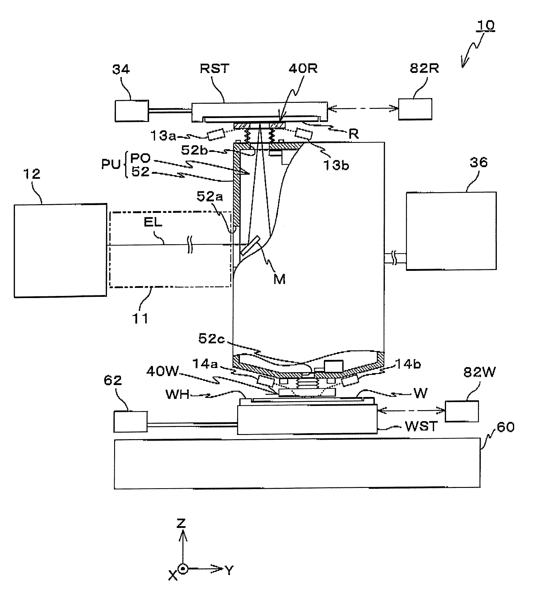
[0068]FIG. 1 schematically shows the entire configuration of an exposure apparatus 10 of the first embodiment. Exposure apparatus10 transfers the entire circuit pattern of a reticle R onto each of a plurality of shot areas on a wafer W by the step-and-scan method, by relatively scanning reticle R and wafer W in a one-dimension direction (in this case, a Y-axis direction) with respect to a projection unit PU while projecting a part of the circuit pattern formed on reticle R via a projection optical system PO in projection unit PU on wafer W.

[0069]Exposure apparatus 10 is equipped with a light source device 12 that emits a EUV light (light in the soft X-ray region) EL, an illumination optical system including a bending mirror M that reflects EUV light EL from light source device 12 and bends the light so that the light is incident on a patterned surface (the l...

second embodiment

A Second Embodiment

[0144]Next, a second embodiment of the present invention will be described, referring to FIGS. 16 to 24B. Here, the same reference numerals will be used for the same or similar sections as in the first embodiment previously described, and a detailed description thereabout will be omitted.

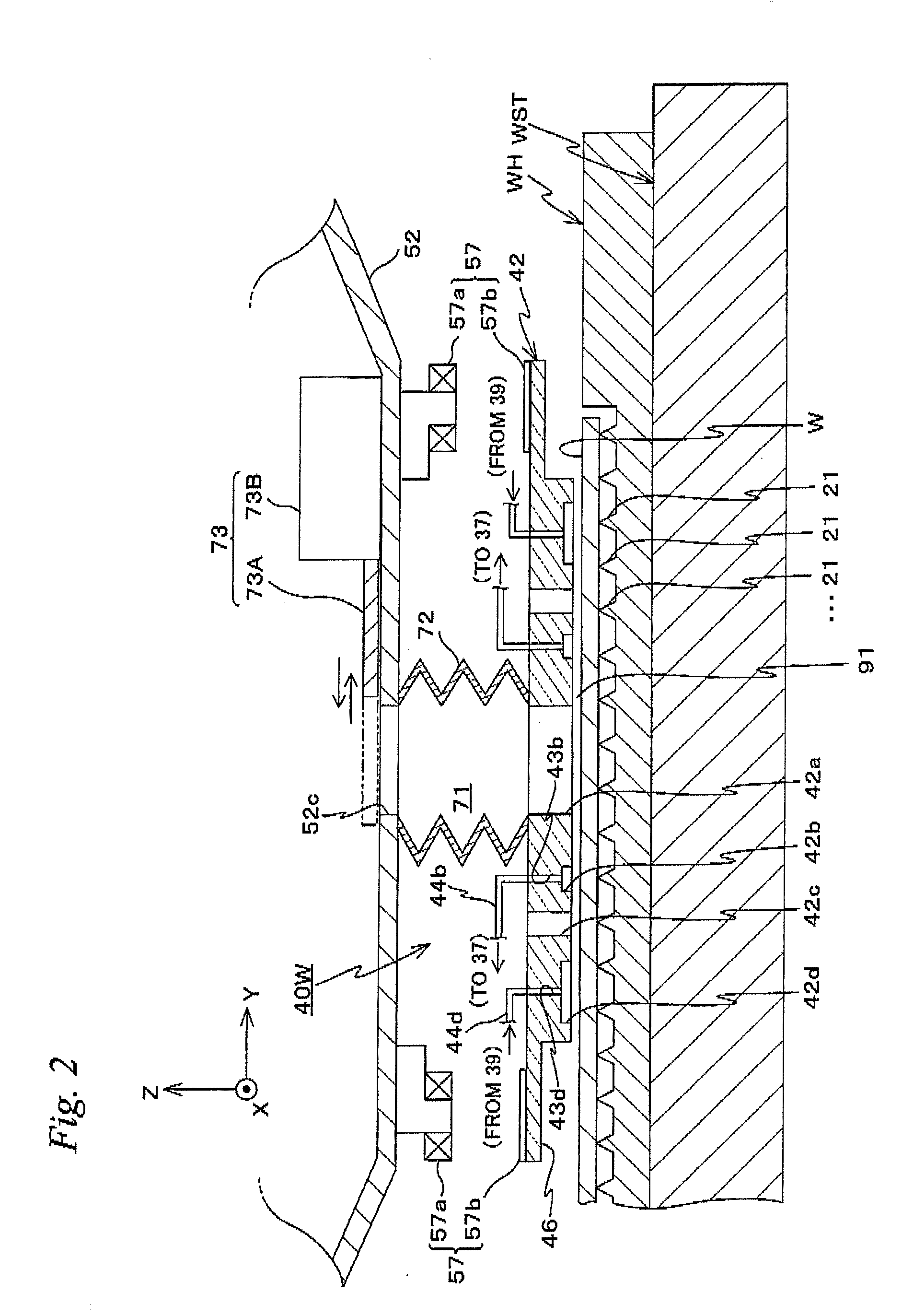
[0145]FIG. 16 schematically shows the entire configuration of an exposure apparatus 10A of the second embodiment. Further, FIG. 17 shows a longitudinal sectional view of a seal unit 40W of the wafer side and its periphery, equipped in exposure apparatus 10A. Further, FIG. 18 shows a longitudinal sectional view of a seal unit 40R of the reticle side and its periphery, equipped in exposure apparatus 10A. Further, FIG. 19 is a block diagram showing an arrangement of a control system in exposure apparatus 10A.

[0146]Similar to exposure apparatus 10, exposure apparatus 10A transfers the entire circuit pattern of a reticle R onto each of a plurality of shot areas on a wafer W by the step...

third embodiment

A Third Embodiment

[0183]Next, a third embodiment of the present invention will be described, referring to FIGS. 25 to 34B. Here, the same reference numerals will be used for the same or similar sections as in the first embodiment previously described, and a detailed description thereabout will be omitted or simplified.

[0184]FIG. 25 schematically shows the entire configuration of an exposure apparatus 10B of the third embodiment. Similar to exposure apparatus 10 and 10A previously described, exposure apparatus 10B transfers the entire circuit pattern of a reticle R onto each of a plurality of shot areas on a wafer W by the step-and-scan method, by relatively scanning reticle R and wafer W in a one-dimension direction (the Y-axis direction) with respect to a projection optical system PO while projecting a part of the circuit pattern formed on reticle R via projection optical system PO on wafer W.

[0185]As it can be seen when comparing FIG. 25 and FIG. 1, exposure apparatus 10B is basic...


PUM


Abstract

The upper end of a static gas bearing member of a wafer side seal unit is connected to an edge section on the outgoing side of an exposure beam of a chamber in an air tight state via bellows, and the lower end surface is in a state forming a predetermined clearance with a wafer and a wafer holder. By this arrangement, the inside of the chamber is isolated from the outside. Accordingly, it becomes possible to maintain a vacuum environment in the periphery of the optical path of the exposure beam without arranging a vacuum chamber to house a wafer, a wafer holder, and a wafer stage, which allows the size of the entire exposure apparatus to be reduced, and also makes it easy to have access to the vicinity of the wafer stage.

Description

CROSS-REFERENCE TO RELATED APPLICATIONS[0001]This non-provisional application claims the benefit of Provisional Applications No. 60 / 924,059 and No. 60 / 924,060 filed Apr. 27, 2007, and Provisional Applications No. 60 / 924,137, No. 60 / 924,142, and No. 60 / 924,143 filed May 1, 2007, the disclosures of which are hereby incorporated herein by reference in its entirety.BACKGROUND OF THE INVENTION[0002]1. Field of the Invention[0003]The present invention relates to movable body apparatus, exposure apparatus and optical system units, and more particularly to a movable body apparatus that is equipped with a movable body which moves holding an object, an exposure apparatus that irradiates an energy beam on the object via an optical system and forms a predetermined pattern on the object and an optical system unit suitable for use in the exposure apparatus, and a device manufacturing method using the exposure apparatus.[0004]2. Description of the Background Art[0005]Conventionally, in a lithograp...

Claims


Application Information

Patent Timeline
IPC IPC(8): G03B27/52
CPCF16C29/025F16C32/0603G03F7/70808G03F7/7085G03F7/70841G03F7/70866G03F7/70816
Inventor TANAKA, KEIICHIKAKIZAKI, YUKIO
Owner NIKON CORP
Why Eureka
Try Eureka