
Exposure device with mechanism for forming alignment marks and exposure process conducted by the same

a technology of alignment marks and exposure devices, which is applied in the field of exposure devices, can solve problems such as trouble, loose tapes, and inability to provide perforation for all tapes

Active Publication Date: 2009-03-05
ORC MFG
View PDF7 Cites 19 Cited by
  • Summary
  • Abstract
  • Description
  • Claims
  • Application Information

AI Technical Summary

Benefits of technology

[0013]The exposure device of the first aspect successfully eliminates the need for a mechanism that forms alignment holes onto a tape. Instead, it forms the alignment marks on the object before an exposure step. Accordingly, this exposure device reduces the risk of generating and spreading dust or contaminants.
[0038]In conclusion, with the exposure device of the present invention and the exposure process executed by said exposure device, circuit patterns of a mask can be transferred to an object precisely without generating and spreading contaminants.

Problems solved by technology

During this process, some troubles are prone to occur, such as the tape are loosened or angled while being pulled out.
However, all of the tapes are not provided with perforation.
Furthermore, the perforation of the tape may be damaged when the teeth of the sprockets are inserted into the holes of the perforation.
Such damaged perforation is prone to deteriorate the accuracy of the alignment process.
Therefore, the mechanism for forming alignment holes is likely to spread dust.
The dust may be adhered to the tape by means of static electricity, thereby leading to the deterioration of resolution of the exposed patterns.

Method used


Image

  • Exposure device with mechanism for forming alignment marks and exposure process conducted by the same
  • Exposure device with mechanism for forming alignment marks and exposure process conducted by the same
  • Exposure device with mechanism for forming alignment marks and exposure process conducted by the same

Examples


Embodiment Construction

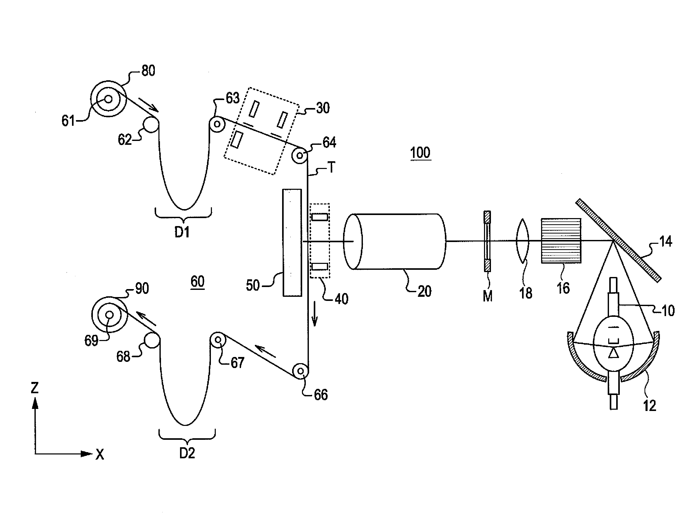
[0054]A description will be given below, of a projection exposure device according to an embodiment of the present invention.

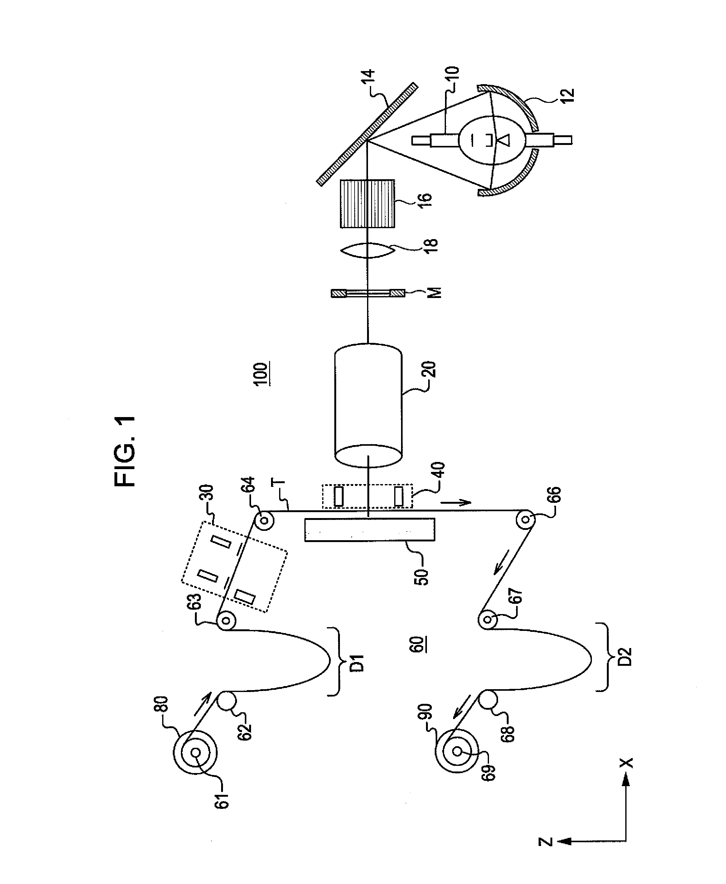
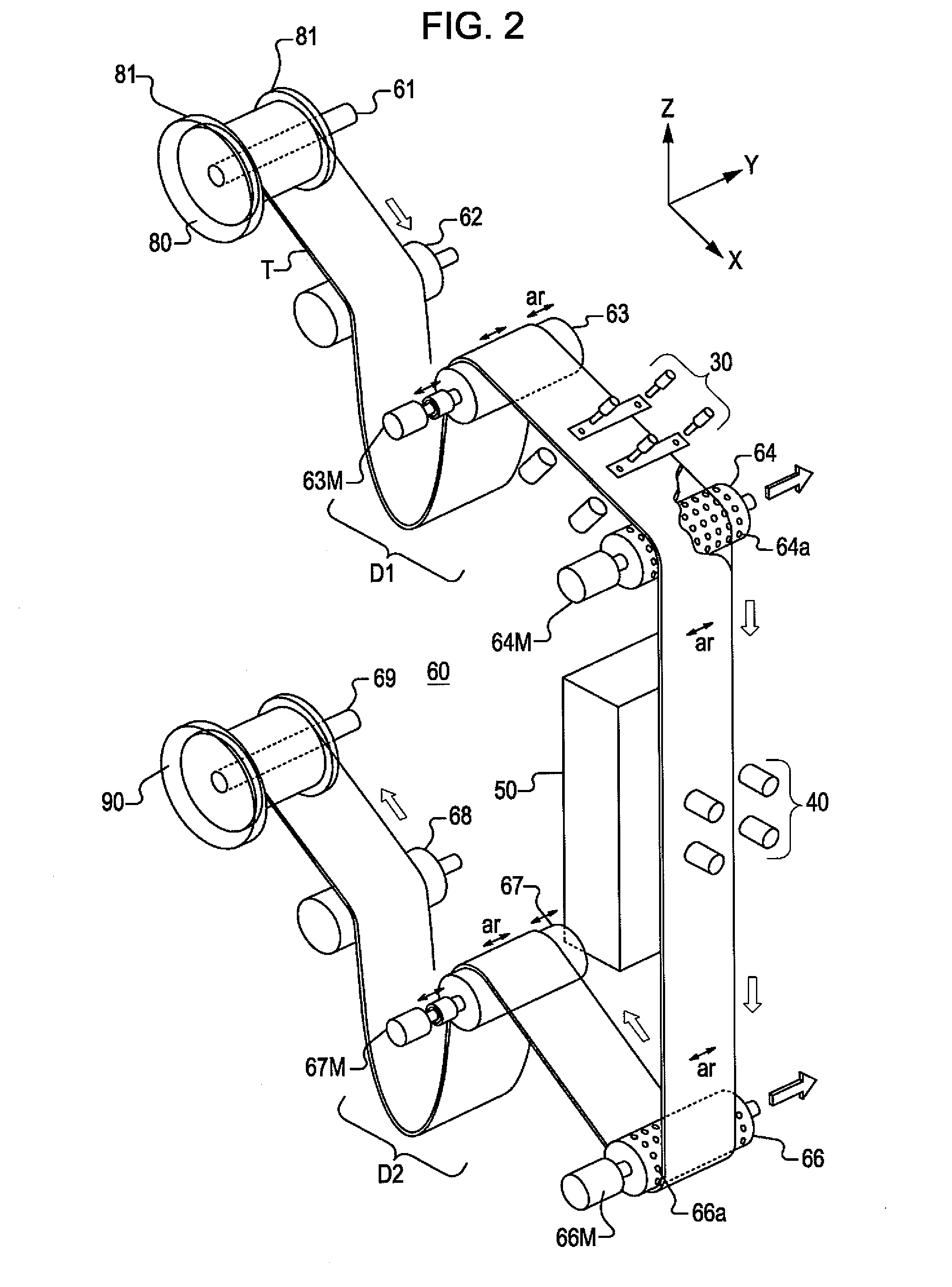
[0055]FIG. 1 is a schematic view of a projection exposure device 100 according to an embodiment of the present invention. The projection exposure device 100 is configured to feed a film-shaped tape T (thereinafter called “tape T”) and to transfer circuit patterns of a photo mask M to the surface of the tape T.

[0056]The tape T is made of a flexible board for electronic circuit boards or a film-shaped tape material. This tape T has a thin, wide shape and, specifically has a width of about 160 mm and a whole length of about 200 m. The tape T is wound around a supply reel rotation section 61, and it is provided with (but not limited to) perforation holes on both sides. Moreover, the tape T has a surface on which a photoresist is coated. The sensitivity of the photoresist matches with the wavelength of the light from a mercury lamp 10 (which will be described later...


PUM


Abstract

The present invention relates to an exposure device for transferring circuit patterns of a mask to a roll-film-shaped object. The exposure device includes a supply reel rotation section that is constituted by a supply reel around which the object is wound and that feeds the object by rotating the supply reel, at least one guide roller for guiding the object fed from the supply reel rotation section, an exposure stage on which the circuit patterns are transferred to the object guided by the guide roller, and an alignment mark forming section which forms, on the object, alignment marks that are used to align the mask with the object and which is positioned between the guide roller and the exposure stage.

Description

CROSS-REFERENCE TO RELATED APPLICATIONS[0001]This application claims the benefit of Japanese Patent Application 2007-219250 filed on Aug. 27, 2007, the disclosure of which is incorporated herein by reference.BACKGROUND OF THE INVENTION[0002]1. Field of the Invention[0003]The present invention relates to an exposure device which handles a roll-film tape and which is equipped with a mechanism for feeding the tape from a supply unit to a winding unit through an exposure stage. Furthermore, the present invention pertains to an exposure process to be executed by said exposure device.[0004]2. Description of the Related Art[0005]In order to achieve their compact and lightweight bodies, small electrical devices, such as portable phones and mobile devices, contain electronic circuit boards made of highly precise, thin film-shaped tapes (thereinafter called “tapes”).[0006]Tapes of this type have a thin, wide and very long shape. Specifically, tapes have a thickness of 0.06 mm to 0.1 mm, but s...

Claims


Application Information

Patent Timeline
IPC IPC(8): G03B27/42
CPCG03F7/2002G03F9/708H01L2924/0002G03F9/7084G03F9/7088H05K1/0269H05K1/0393H05K3/0008H05K3/0082H05K3/064H05K2201/09918H05K2203/0505H05K2203/0557H05K2203/056H05K2203/1545H01L2924/00
Inventor SATO, JINYAMAGA, MASARU
Owner ORC MFG
Learn More