Optical Pickup Device

a pickup device and optical technology, applied in the field of optical pickup devices, can solve the problems of inability to normally record or play back information, inability to adjust the spherical aberration, and the flexibility of configuring the optical system becomes extremely low, and achieve the effect of controlling the diffraction efficiency

Active Publication Date: 2009-03-05
RAKUTEN GRP INC
View PDF5 Cites 2 Cited by
  • Summary
  • Abstract
  • Description
  • Claims
  • Application Information

AI Technical Summary

Benefits of technology

[0025]Two or more such phase correcting zones are concentrically provided for each of the light beams to be phase-corrected. With this configuration, good point image light intensity distribution free of side lobes is achieved.
[0026]Each phase correcting zone of the phase correcting means is configured to be a diffraction optical region exhibiting a kinoform shape or a pseudo-kinoform shape having stepped structures with two or more steps in cross section. This configuration makes it possible to select a wavelength and correct aberration and control the diffraction efficiency using the number of steps of each stepped structure.
[0027]If the phase correcting means is desired to perform phase correction on the two light beams and propagate the specific one light beam without performing phase correction and changing its parallel light beam state, each phase corre...

Problems solved by technology

Accordingly, if a common objective lens is used, spherical aberration cannot be corrected, and it is impossible to normally record or play back in...

Method used


Image

  • Optical Pickup Device
  • Optical Pickup Device
  • Optical Pickup Device

Examples


first embodiment

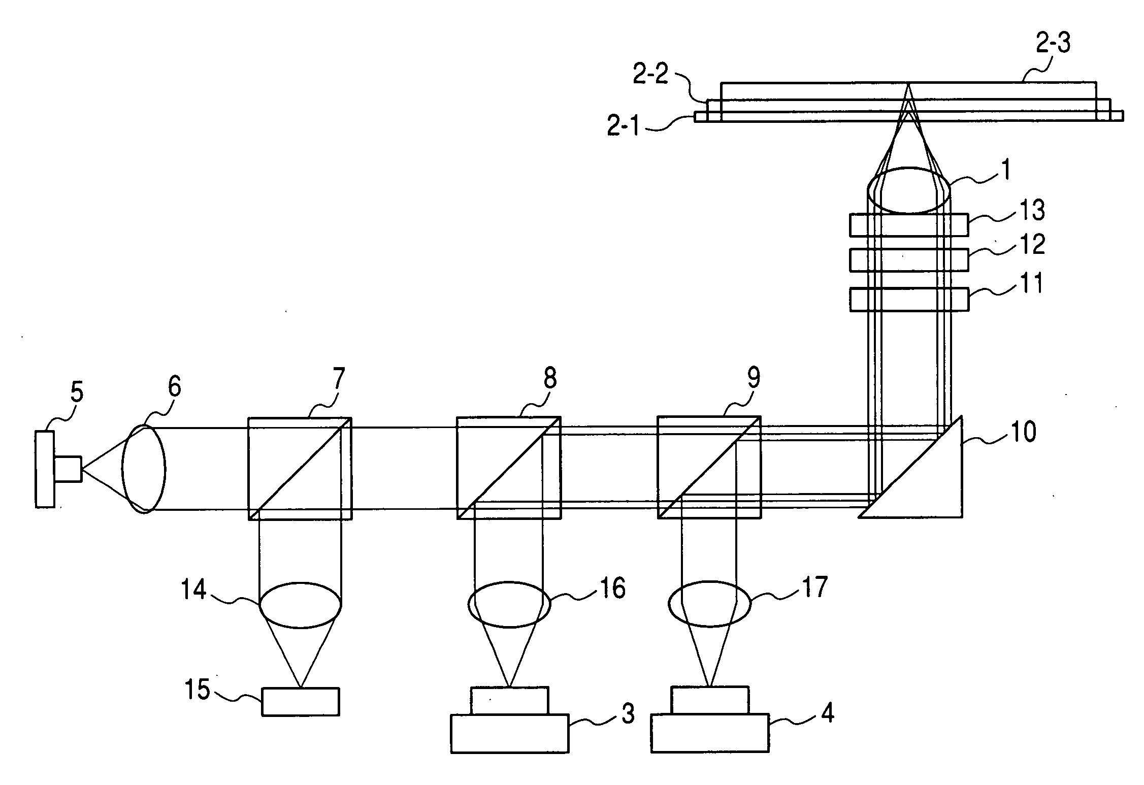
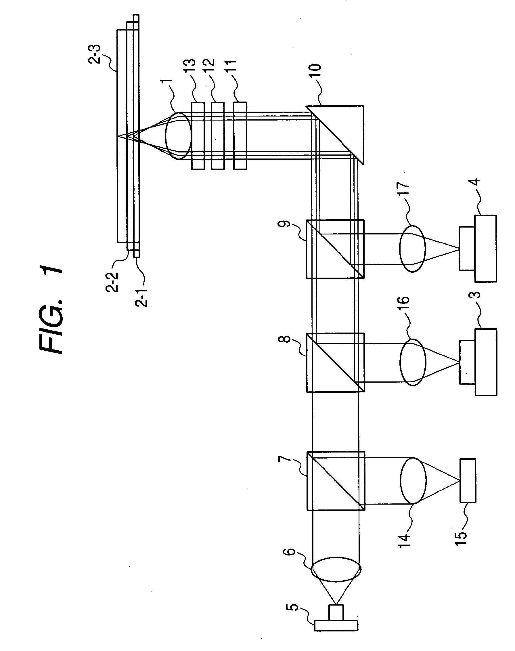
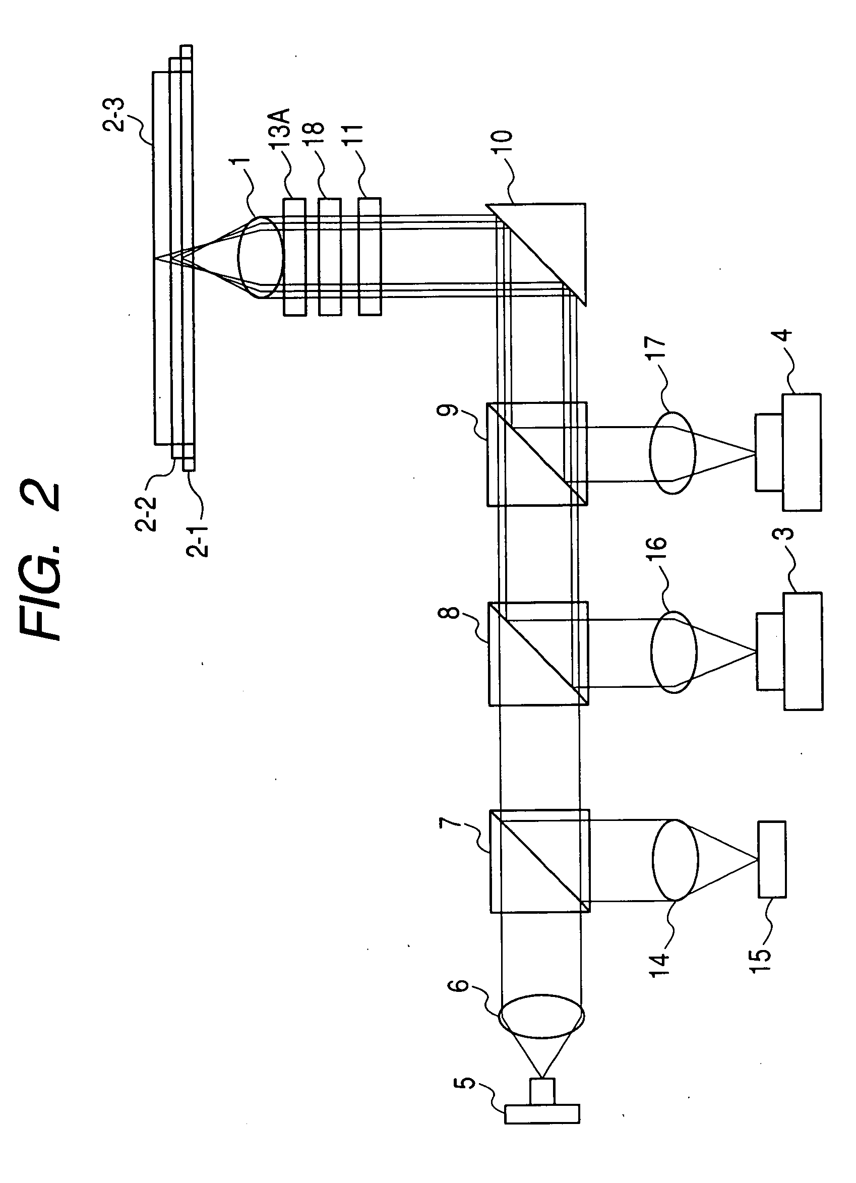
[0058]FIG. 2 is a view of the configuration of an optical pickup device for explaining the principle of the present invention. The same components as those in FIG. 1 are denoted by the same reference numerals.

[0059]In FIG. 2, an objective lens 1 is designed such that the wave front aberration to light having a wavelength λ0 corresponding to a next generation DVD having a used wavelength λ0 of 405 nm, a NA of 0.85, and a signal plane protecting substrate thickness of 0.1 mm is minimum on the signal plane of a next generation DVD when the light is incident as a parallel light beam. A DVD hologram module 3 and a CD hologram module 4, in each of which light receiving and emitting units are packaged, are used as DVD and CD light sources. A light beam radiated from a next generation DVD semiconductor laser 5 is transformed into a parallel light beam by a collimator lens 6, passes through a deflection beam splitter 7 and DVD and CD dichroic prisms 8 and 9 for light beam separation, and cha...


PUM


Abstract

An optical pickup device enables prevention of an increase of spherical aberration during tracking without needing any finite optical system. The diameters of parallel light beams (A, B, C) for the next-generation DVDs, DVDs, and CDs are limited to diameters of a, b, c (a>b>c) in accordance with the NA for each type by a light beam limiting element, the diameter of light beam B is limited to the diameter ranges of b to c and d (=0.85×c) to e (d>e>0), the diameter of the light beam C is limited to the diameter ranges of c to d and less than e. They are passed through a phase correcting element (13B) and focused on the corresponding optical recording medium signal planes by means of a common objective lens. The objective lens is so optimized that the wave front aberration to the light beam A is minimum on the signal plane of the next generation DVD. The phase correcting element (13B) has a phase correcting zones (Z1 to Z4) of diffraction optical structure exhibiting a pseudo-kinoform shape of a step constitution. The spherical aberration to the light beam B is corrected in the zones (Z1, Z3). The spherical aberration to the light beam C is corrected in the zones (Z2, Z4). The light beam A is passed through all the zones of the light beam diameter a without changing the parallel light beam state by optimizing the step heights of the zones (Z1 to Z4).

Description

TECHNICAL FIELD[0001]The present invention relates to an optical pickup device and, more particularly, to an optical pickup device which guides each of a plurality of light beams having wavelengths different from one another corresponding to a plurality of optical recording media having specifications different from one another to a common objective lens and focuses the light beams on an optical recording medium.BACKGROUND ART[0002]CDs and DVDs (digital versatile disks) currently in widespread use each have a capacity of several hundreds of megabytes to several gigabytes. The development and commercialization of next generation DVDs (also referred to as high-definition DVDs) which are optical recording media having a larger capacity of several tens of gigabytes are under way in response to a recent increase of the quality of images. Along with a demand for smaller size and lower cost, an optical pickup which records data on and / or plays back data from a next generation DVD is desire...

Claims


Application Information

Patent Timeline
IPC IPC(8): G11B7/135
CPCG11B7/1353G11B2007/0006G11B7/13922G11B7/1367
Inventor SHINZOU, TORU
Owner RAKUTEN GRP INC
Why Eureka
Try Eureka