Condenser microphone

Inactive Publication Date: 2009-03-05
YAMAHA CORP
View PDF5 Cites 32 Cited by
  • Summary
  • Abstract
  • Description
  • Claims
  • Application Information

AI Technical Summary

Benefits of technology

[0014]It is an object of the present invention to provide a

Problems solved by technology

Sound waves propagating towards the backside of the diaphragm degrade the sensitivity of the condenser microphone.
In this case, the contact area between the diaphragm and the substrate is limited.
As the contact area

Method used


Image

  • Condenser microphone
  • Condenser microphone
  • Condenser microphone

Examples


Example

[0058]The present invention will be described in further detail by way of examples with reference to the accompanying drawings.

1. Constitution

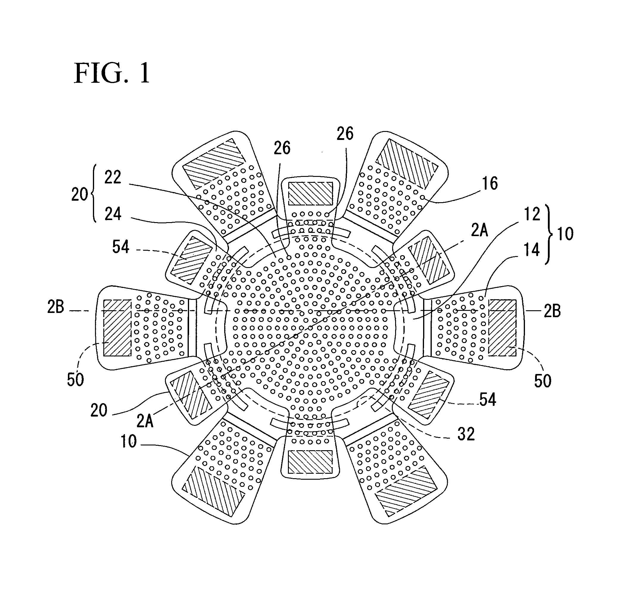
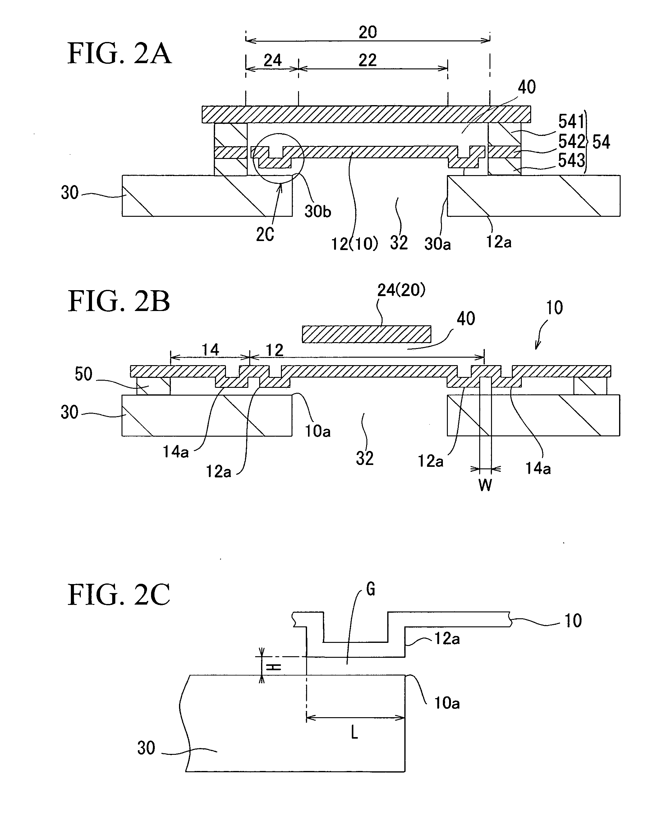
[0059]FIG. 1 is a plan view showing a MEMS structure of a condenser microphone in accordance with a preferred embodiment of the present invention. FIG. 2A is a sectional view taken along line 2A-2A in FIG. 1; and FIG. 2B is a sectional view taken along line 2B-2B in FIG. 1.

[0060]The condenser microphone of the present embodiment includes a diaphragm 10 and a plate 20 (which form a parallel-plate condenser), a substrate 30, a plurality of first supports 50 (for supporting the diaphragm 10 above the substrate 30), and a plurality of second supports 54 (for supporting the plate 20 above the substrate 30).

[0061]The substrate 30 is a monocrystal silicon substrate whose thickness ranges from 500 μm to 600 μm, for example. A through-hole 30a forming a side wall of a back cavity 32 is formed to run through the substrate 30. An opening 30b of the throu...


PUM


Abstract

A condenser microphone includes a substrate having an opening in a back cavity, a diaphragm including a center portion and a plurality of arms extended in the radial direction from the center portion, a plate positioned opposite the diaphragm, and a support structure for supporting the periphery of the diaphragm and the periphery of the plate above the substrate while insulating the diaphragm and the plate both having conductive properties from each other. The support structure forms gaps between the substrate, the diaphragm, and the plate. Projections having insulating properties are formed in the center portion and the arms of the diaphragm so as to project towards the substrate and are separated from each other in the circumferential direction of the diaphragm. This prevents the diaphragm from being unexpectedly adhered and fixed to the substrate, thus improving the sensitivity of the condenser microphone.

Description

BACKGROUND OF THE INVENTION[0001]1. Field of the Invention[0002]The present invention relates to condenser microphones serving as micro-electro-mechanical-system (MEMS) microphones.[0003]The present application claims priority on Japanese Patent Application No. 2007-206462, the content of which is incorporated herein by reference.[0004]2. Description of the Related Art[0005]Conventionally, various types of miniature silicon condenser microphones have been manufactured by way of semiconductor device manufacturing processes. They are disclosed in various documents such as Patent Document 1, Patent Document 2, Patent Document 3, and Non-Patent Document 1.[0006]Patent Document 1: Japanese Patent Application Publication No. H09-508777[0007]Patent Document 2: Japanese Patent Application Publication No. 2004-506394[0008]Patent Document 3: U.S. Pat. No. 4,776,019[0009]Non-Patent Document 1: MSS-01-34 published by Japanese Institute of Electrical Engineers[0010]The aforementioned condenser m...

Claims


Application Information

Patent Timeline
IPC IPC(8): H04R25/00
CPCH04R31/00H04R19/005H04R7/06H04R19/04H04R31/006
Inventor HIRADE, SEIJISUZUKI, TAMITOOMURA, MASAYOSHIEBIHARA, YUUSAKU
Owner YAMAHA CORP
Why Eureka
Try Eureka