Image Detection Method

a detection method and image technology, applied in the field of image detection methods, can solve the problems that the current monitoring system cannot detect such abnormal phenomena, and consider them abnormal, and achieve the effect of prolonging reducing the interval of performing the step of detecting image chang

Inactive Publication Date: 2009-03-05
MICRO-STAR INTERNATIONAL
View PDF9 Cites 3 Cited by
  • Summary
  • Abstract
  • Description
  • Claims
  • Application Information

AI Technical Summary

Benefits of technology

[0011]The image detection method according to a preferred embodiment of the present invention further includes setting a detection frequency parameter, so as to control the frequency for detecting the image change. That is, the frequency of performing the step of detecting the image change is set. When the first and second signals are continuously received by the monitoring system, nothing abnormal occurs to the monitored region. Therefore, the detection frequency parameter is automatically reduced by the system, such that the interval of performing the step of detecting the image change is prolonged. When the third and fourth signals are continuously received, something abnormal continuously occurs to the monitored region. Therefore, the detection frequency parameter is automatically increased by the system, such that the interval of performing the step of detecting the image change is shortened.

Problems solved by technology

As the monitoring system operates manually, human mistakes may easily occur (for example, the departure of the manager from the central monitoring screen), thus greatly alleviating the efficacy of the monitoring system (fail to detect strangers passing through the gateway).
However, the aforementioned system only performs detection determination when “actions occur” in the monitored region, and whether or not there is an abnormal action is fed back.
Actually, in some situations, for example, in a health care monitoring system for the old living alone, it is considered an abnormal phenomenon if there is no image change in some special areas, such as the washing room or the bed, for a long time.
Nevertheless, the current monitoring system cannot detect such abnormal phenomena.

Method used


Image

  • Image Detection Method
  • Image Detection Method
  • Image Detection Method

Examples


first embodiment

The First Embodiment

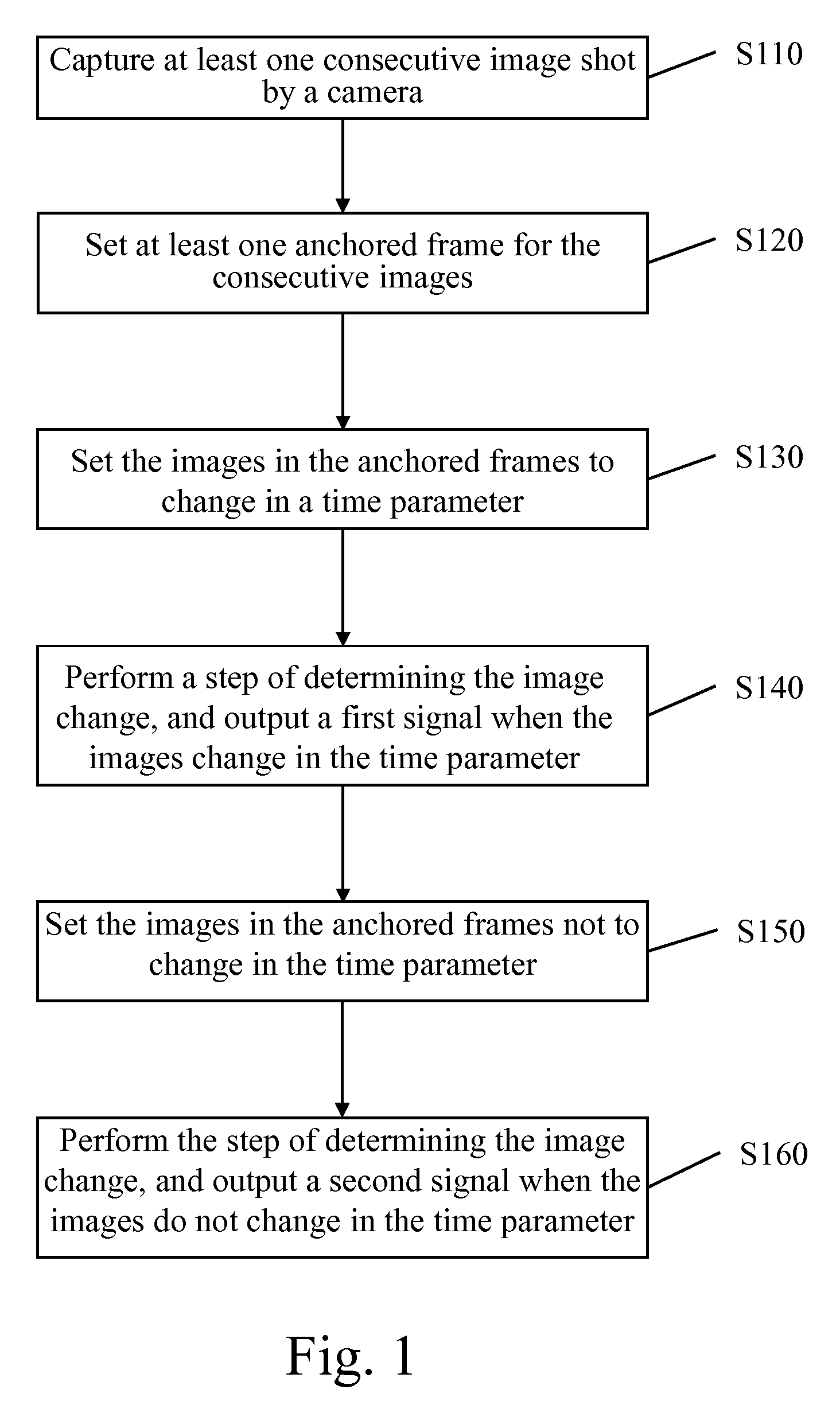
[0020]FIG. 1 is a flow chart of an image detection method. Referring to FIG. 1, in the first embodiment, the image detection method includes: first, capturing at least one consecutive image shot by a camera (Step S10); then, setting at least one anchored frame for the consecutive images (Step S120); next, setting the images in the anchored frames to change in a time parameter (Step S130); at this time, performing a step of determining the image change, and outputting a first signal when the images change in the time parameter (Step S140); finally, setting the images in the anchored frames not to change in the time parameter (Step S150); at this time, performing the step of determining the image change, and outputting a second signal when the images do not change in the time parameter (Step S160).

[0021]Accordingly, a third signal is output when the images in the anchored frames are set to change in a period of time but do not change, and on the contrary, a fourth ...

second embodiment

The Second Embodiment

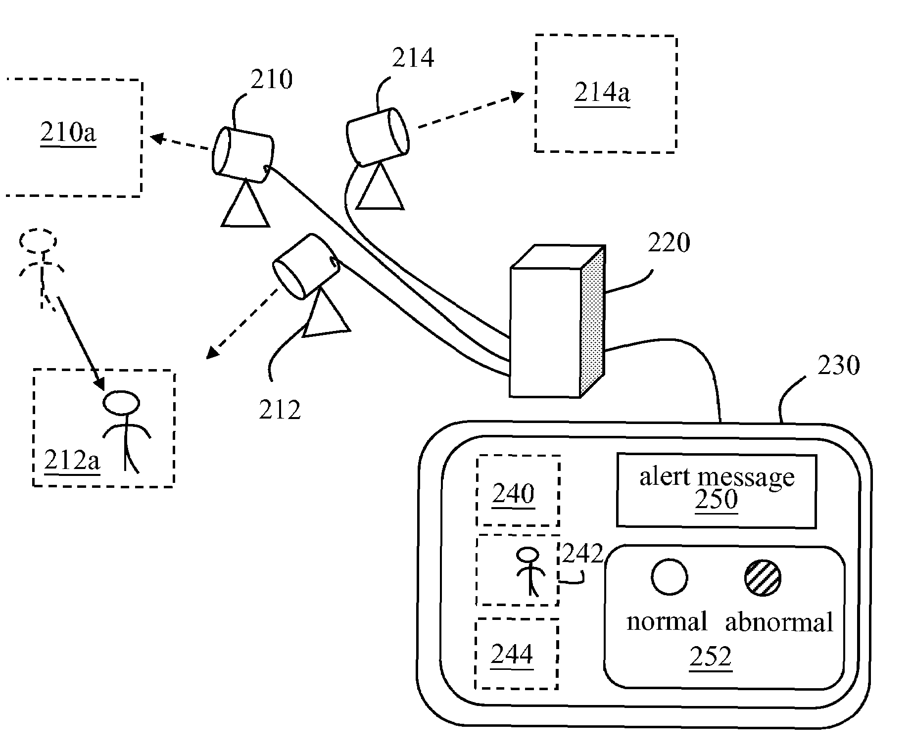
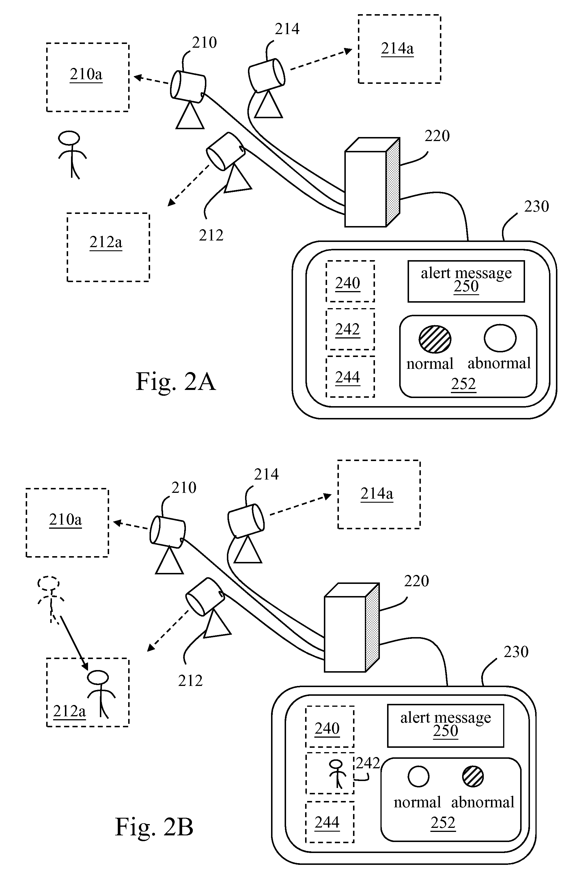
[0027]A practical example is provided by the second embodiment to clearly illustrate the technique of the present invention. FIGS. 2A and 2B are schematic views of the system architecture of applying the image detection method to a remote detection system. Sequentially referring to FIG. 2A and FIG. 2B, in this preferred embodiment, three cameras (210, 212, 214) are used to respectively monitor three monitored regions (210a, 212a, 214a), and send the shot pictures to a computer 220 to be displayed on a screen 230. Before shooting, the user adopts an image detection application software installed in the computer 220 to set anchored frames (240, 242, 244), and the anchored frames are regions in the pictures that the user is interested in. The screen 230 not only shows the anchored frames (240, 242, 244) in the shot pictures, but also other stuffs such as an alert message 250 and an alert lamp 252. Referring to FIG. 2A, nobody is allowed to enter or exit from the se...

third embodiment

The Third Embodiment

[0029]In a third embodiment, for example, the image detection method is applied to an interactive computer game, like Dance Dance Revolution (DDR). FIGS. 3A and 3B are schematic views of the system architecture of applying the image detection method to an interactive computer game system. Sequentially referring to FIG. 3A and FIG. 3B, the game goes like this: a user stands in the region detectable by a camera 310, and moves following the hints shown by arrows on a screen 330. If the player finishes the movements exactly according to the hints, a high score is given and the game is over.

[0030]The camera 310 shoots the monitored region (i.e., the moving range of the player), and transmits the shot images to a computer 320. The monitored region 310a is divided into multiple anchored frames (312, 314, 316, 318), corresponding to arrows in the front row of the screen (arrows indicating four directions of up, down, left, and right). During the game, movements are desig...


PUM


Abstract

An image detection method is performed by a computer to determine whether or not an image in a region shot by a camera changes. According to the method, consecutive images shot by the camera are captured, and at least one anchored frame for the consecutive images is set. Whether or not the images in the anchored frame should or should not change is determined, and a signal is transmitted to determine whether or not the detected region is normal or not. Then, a notification signal is transmitted automatically to remind supervisors to closely observe the detected region.

Description

CROSS-REFERENCE TO RELATED APPLICATIONS[0001]This non-provisional application claims priority under 35 U.S.C. § 119(a) on Patent Application No(s). 096132140 filed in Taiwan, R.O.C. on Aug. 29, 2007, the entire contents of which are hereby incorporated by reference.BACKGROUND OF THE INVENTION[0002]1. Field of Invention[0003]The present invention relates to an image detection method, and more particularly to an image detection method of transmitting detection normal / abnormal signals according to image changes in a detected region within a set period of time.[0004]2. Related Art[0005]With the improvement of digital photography technique and large decrease of the prices of digital photography related equipments, digital photography has been widely applied in people's daily life. So-called digital photography generally refers to a shooting method to convert the shot characters and scenes into a digital file and store the digital file into a storage medium. For example, Web CAM, digital ...

Claims


Application Information

Patent Timeline
Patent Type & Authority Applications(United States)
IPC IPC(8): G06K9/00
CPCG08B13/196G08B13/194
Inventor LEE, PIN-CHANGHSU, RUEI-CHANG
Owner MICRO-STAR INTERNATIONAL
Why Eureka
Try Eureka