Independent Separating Type Power Battery Assembly

a power battery and independent technology, applied in the direction of batteries, cell components, cell component details, etc., can solve the problems of difficult improvement of electric power of conventional power battery assembly, wires occupying too much space, and serious dangers

Active Publication Date: 2009-03-05
BIXIANG ELECTRIC ENERGY HIGH SCI & TECHCO
View PDF10 Cites 10 Cited by
  • Summary
  • Abstract
  • Description
  • Claims
  • Application Information

AI Technical Summary

Benefits of technology

[0012]The primary objective of the present invention is to provide an independent separating type power battery assembly which solves the conventional problem of security caused by the breaking of a single battery.

Problems solved by technology

Firstly, since the plurality of batteries in parallel connection is installed in one box, the parallel circuit is complex. And with the increase of the batteries, the number of the parallel circuits will be multiplied. As a result, the wires will occupy too much space, and this is the main reason why the electric power of the conventional power battery assembly is difficult to improve.
Secondly, if any of the batteries is broken, which will not only produce excessive current to destroy the circuit equipment of the mechanism, but also will produce high heat to cause serious dangers.
However, such a power battery assembly will cause other problems.
As a result, the electric vehicle stops at the center of the road, the mobile machine stops at the hazardous area, and the remote control machine loses the return power.
The only solution to the above-mentioned problem is to provide a spare battery system simultaneously, but such a spare battery system will increase the cost and occupy too much space.

Method used


Image

  • Independent Separating Type Power Battery Assembly
  • Independent Separating Type Power Battery Assembly
  • Independent Separating Type Power Battery Assembly

Examples


Embodiment Construction

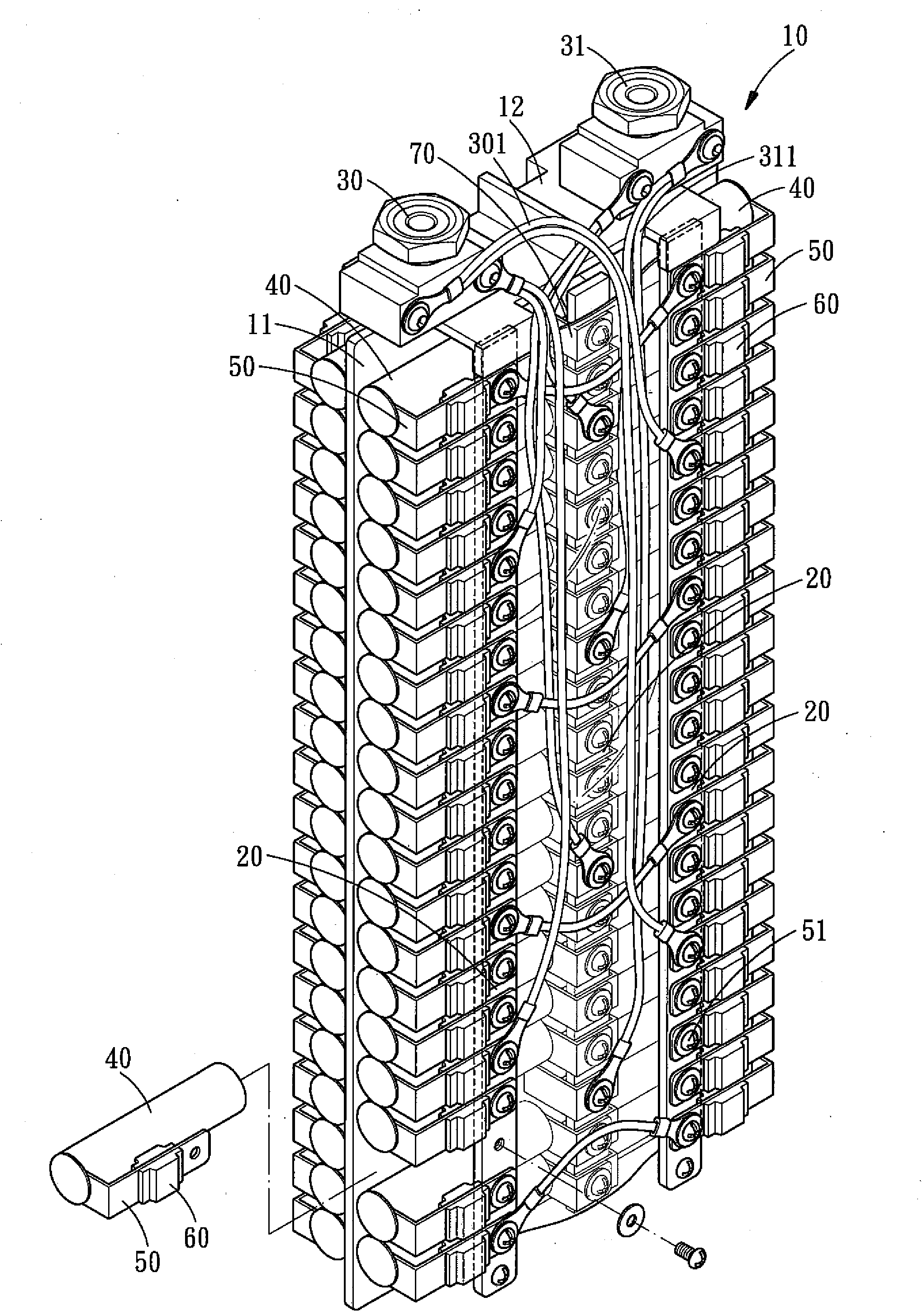
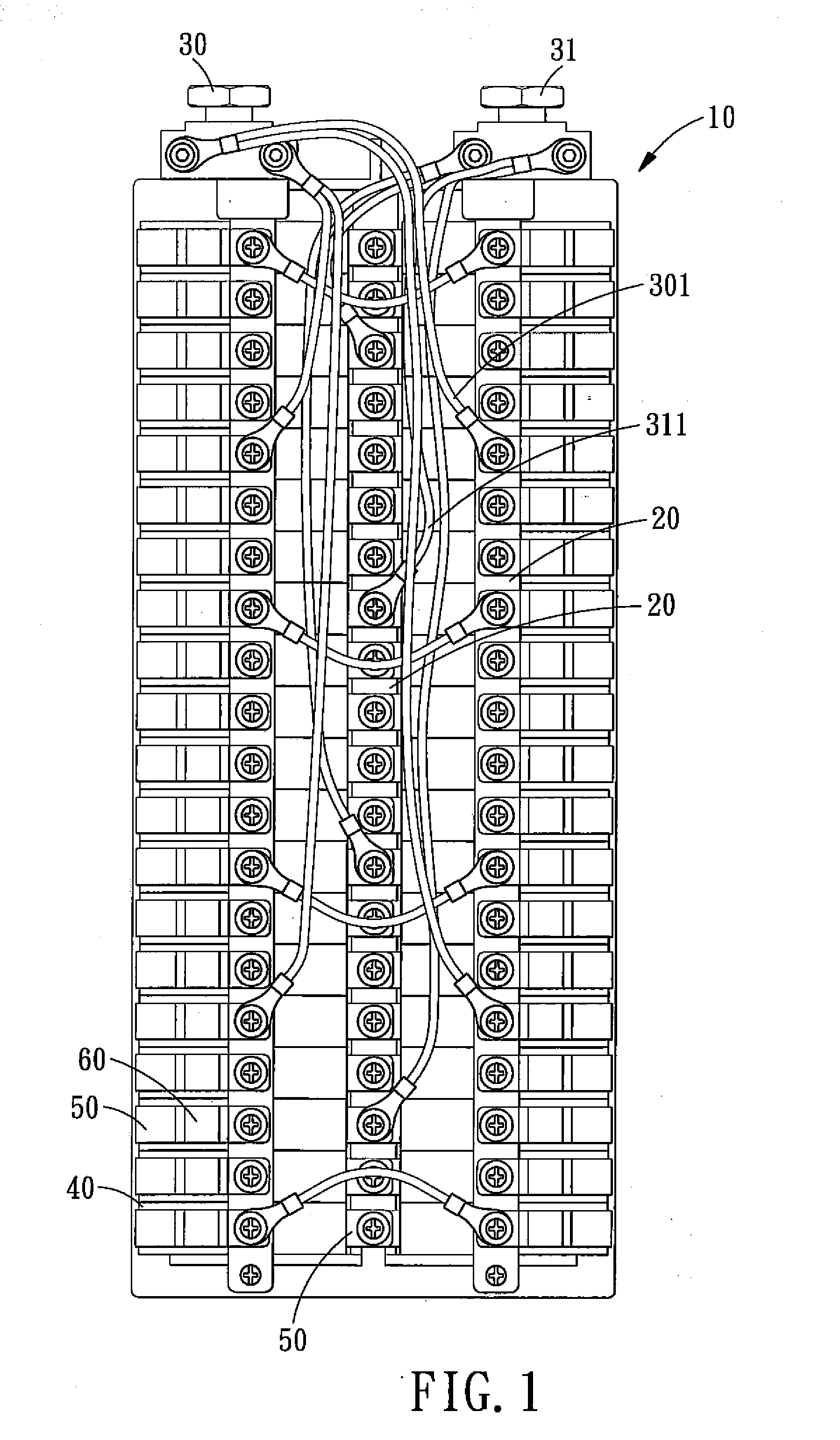
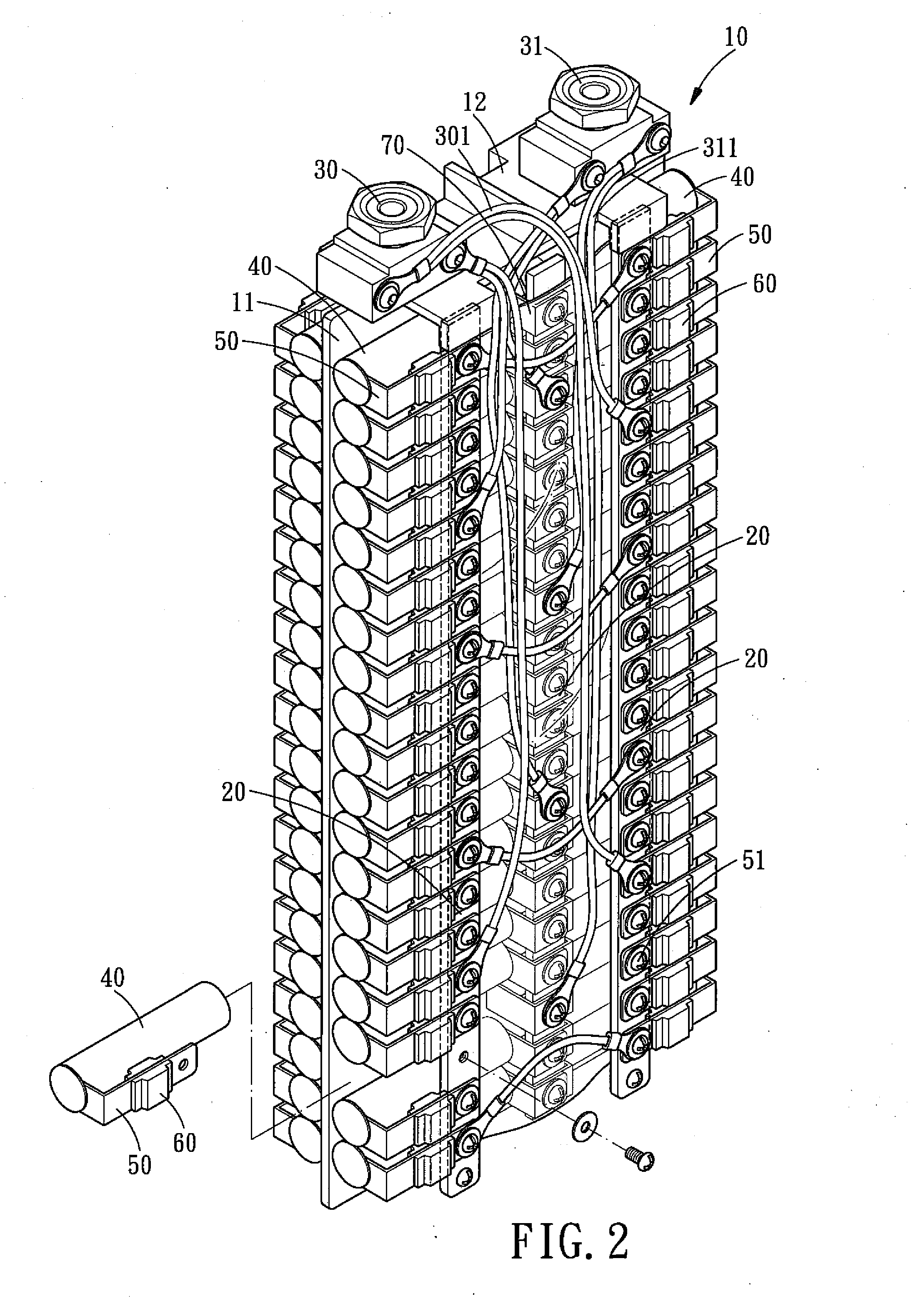
[0029]Referring to FIGS. 1-3, an independent separating type power battery assembly in accordance with the present invention comprises a rack assembly 10, six guiding strips 20, two polar heads 30 and 31, a plurality of lithium batteries 40, a plurality of guiding pieces 50, a plurality of safety units 60, and a plurality of insulators 70.

[0030]The rack assembly 10 is I-shaped and is integrally formed by a separating plate 11 and two side racks 12, and each side rack 12 is defined with three threaded holes.

[0031]Each guiding strip 20 is made of metal with high conductivity, and both ends of each guiding strip 20 are locked in the side racks 12 at both ends of the rack assembly 10 by screws. Both sides of the rack assembly 10 are installed with three guiding strips 20, respectively, that is, a mid guiding strip 20 and two outer guiding strips 20. And a containing space 21 is formed between the three guiding strips 20 and the rack assembly 10 and is located at each side of the rack as...


PUM

PropertyMeasurementUnit
conductivityaaaaaaaaaa
currentaaaaaaaaaa
voltageaaaaaaaaaa

Abstract

An independent separating type power battery assembly comprises a rack assembly, a plurality of guiding strips, two polar heads, a plurality of lithium batteries and safety units. The guiding strips are connected to the polar heads and are disposed on the rack assembly, respectively. The rack assembly has a containing space for accommodating the lithium batteries, and each lithium battery is connected to the guiding strip by a guiding piece via one safety unit, such that the lithium batteries are connected in parallel, thus providing enough power with a small size. In addition, each safety unit can cut off the broken lithium battery separately, so as to avoid the immediate shut-off of the electric power.

Description

BACKGROUND OF THE INVENTION[0001]1. Field of the Invention[0002]The present invention relates to a power battery assembly, and more particularly to an independent separating type power battery assembly which utilizes a rack assembly and a plurality of guiding strips to enable a plurality of lithium batteries to be connected in parallel, and utilizes a plurality of safety units to cut off the broken lithium batteries to avoid the immediate shut-off of the electric power.[0003]2. Description of the Prior Art[0004]Power battery assembly is the battery equipment for providing power to mechanism, and the power battery assembly must has high voltage and big current, such that the power battery assembly can effectively drive the mechanism. And as the only energy to drive the mechanism, the use of power battery assembly is very important to the mechanism.[0005]A plurality of batteries of a conventional power battery assembly is installed in a box after the batteries are connected in paralle...

Claims


Application Information

Patent Timeline
Patent Type & Authority Applications(United States)
IPC IPC(8): H01M6/42H01M50/213H01M50/293H01M50/296
CPCH01M2/1016H01M10/052Y02T10/7011H01M2200/00H01M10/4207Y02E60/10H01M50/293H01M50/213H01M50/296
Inventor WU, DONALD P.H.
Owner BIXIANG ELECTRIC ENERGY HIGH SCI & TECHCO
Why Eureka
Try Eureka