
Battery container unit

a battery container and container technology, applied in the field of battery container units, can solve the problems of inconstant cooling capacity of each battery module, inability to say that the cooling efficiency of each battery module is sufficient, and inability to avoid enlargement of the unit's entire body, so as to reduce manufacturing costs, enhance cooling efficiency, and generate cooling medium more effectively

Inactive Publication Date: 2009-03-05
HONDA MOTOR CO LTD
View PDF4 Cites 29 Cited by
  • Summary
  • Abstract
  • Description
  • Claims
  • Application Information

AI Technical Summary

Benefits of technology

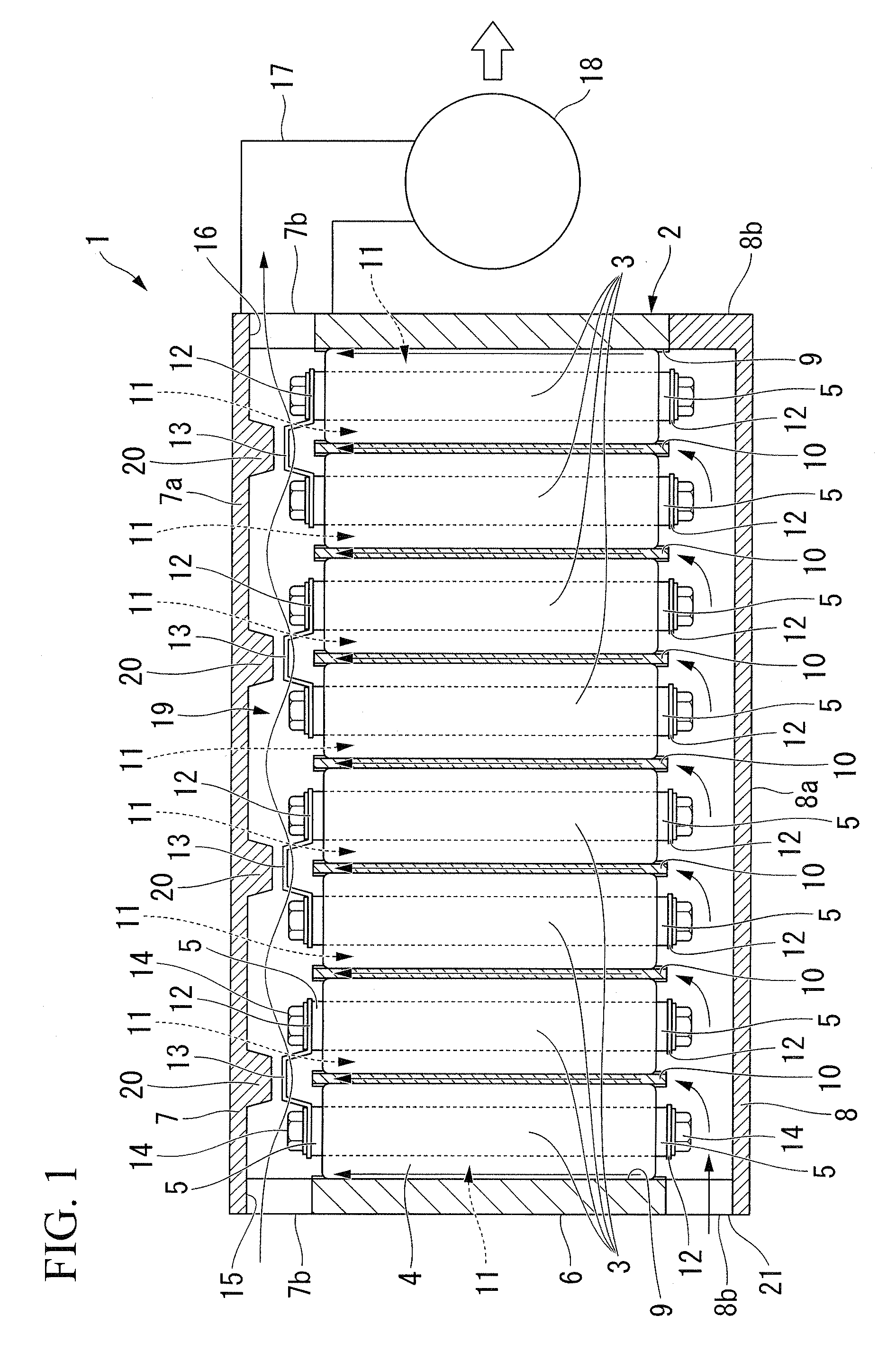
[0013]In addition, from the cooling medium of the first cooling medium flow path which flows linearly in parallel with and along the electrode terminal and with conductive linking member of each battery module, the electrode terminals, release a large amount of heat from inside the battery modules, and the conductive linking members are effectively cooled. In addition, because it is possible to cool the outer peripheral surface of every battery module by the flow of cooling medium in the first cooling medium flow path and by the flow of cooling medium in the second cooling medium flow path, more effective cooling of the battery modules within the enclosure becomes possible. The result is that miniaturization of the entire unit becomes possible.(2) It may be arranged such that: the first cooling medium flow path is provided in a region of the enclosure near a first end in the axial direction of the battery module; and a cooling medium intake opening is provided which communicates with the second cooling medium flow path, in a region of the enclosure near a second end in the axial direction of the battery module.
[0015]Moreover, in this way, while having an extremely simple construction, it is possible to flow cooling medium reliably in the second cooling medium flow path. Consequently, it is possible to further miniaturize the unit and to reduce manufacturing costs.(3) It may be arranged such that: the battery container unit according to claim 2, wherein the conductive linking member includes: a plurality of first conductive linking members each of which links an adjacent pair of the electrode terminals along the flow direction of the cooling medium within the first cooling medium flow path; and a second conductive linking member which is provided across extensions of respective linking lines of two adjacent first conductive linking members, and connects a pair of the electrode terminals in the direction intersecting with the flow direction of the cooling medium.
[0020]In this case, because the cooling medium separator is formed on a wall of the enclosure, it is possible to reduce manufacturing costs by simplifying the construction.(6) It may be arranged such that: two of the first cooling medium flow paths are provided near the first end and the second end respectively in the axial direction of the battery module of the enclosure.
[0021]In this case, both sides of the electrode terminal and the conductive linking member of each battery module are respectively cooled by the cooling medium which flows in the first cooling medium flow paths. In addition, in the second cooling medium flow path, the cooling medium flows towards both of the first cooling medium flow paths from the center of the axial direction of the battery module. In this way, more effective cooling of both sides of the electrode terminal and the conductive linking member of every battery module, which releases a large amount of heat, is possible.(7) It may be arranged such that, in the battery container unit of (6): the conductive linking member includes: a plurality of first conductive linking members each of which links an adjacent pair of the electrode terminals along the flow direction of the cooling medium within the first cooling medium flow path; and a second conductive linking member which is provided across extensions of respective linking lines of two adjacent first conductive linking members, and connects a pair of the electrode terminals in the direction intersecting with the flow direction of the cooling medium.(8) It may be arranged such that, in the battery container unit of (7): the battery container unit further includes a bent cooling medium separator which divides a first cooling medium sub-passage passing along the first conductive linking member and a second cooling medium sub-passage passing along the second conductive linking member.(9) It may be arranged such that, in the battery container unit of (8): the cooling medium separator is formed on a wall within the enclosure facing the first conductive linking member and the second conductive linking member.(10) It may be arranged such that: the battery container unit further includes a flow accelerator, which locally enhances the flow speed of the cooling medium, provided within the first cooling medium flow path in the enclosure.
[0023]Because it is possible to generate flow of cooling medium more effectively in the second cooling medium flow path by the flow accelerator, which was provided within the first cooling medium flow path, it becomes possible to enhance the cooling efficiency on the outer peripheral surface of each battery module.(11) It may be arranged such that: the flow accelerator includes a protrusion protruding from the enclosure along the axial direction of the battery module and facing the conductive linking member.
[0024]In this case, because the flow accelerator is formed by the protrusion provided in the enclosure, it is possible to reduce manufacturing costs by simplifying the construction.

Problems solved by technology

Because of this limitation, one cannot say that the cooling efficiency for each battery module is sufficient.
Accordingly, it is not possible to avoid enlargement of the unit's entire body.
According to this effect, the cooling capability for each battery module becomes inconstant.
It becomes difficult to utilize the capability of the entire battery container module to a maximum.

Method used


Image

  • Battery container unit
  • Battery container unit
  • Battery container unit

Examples


first embodiment

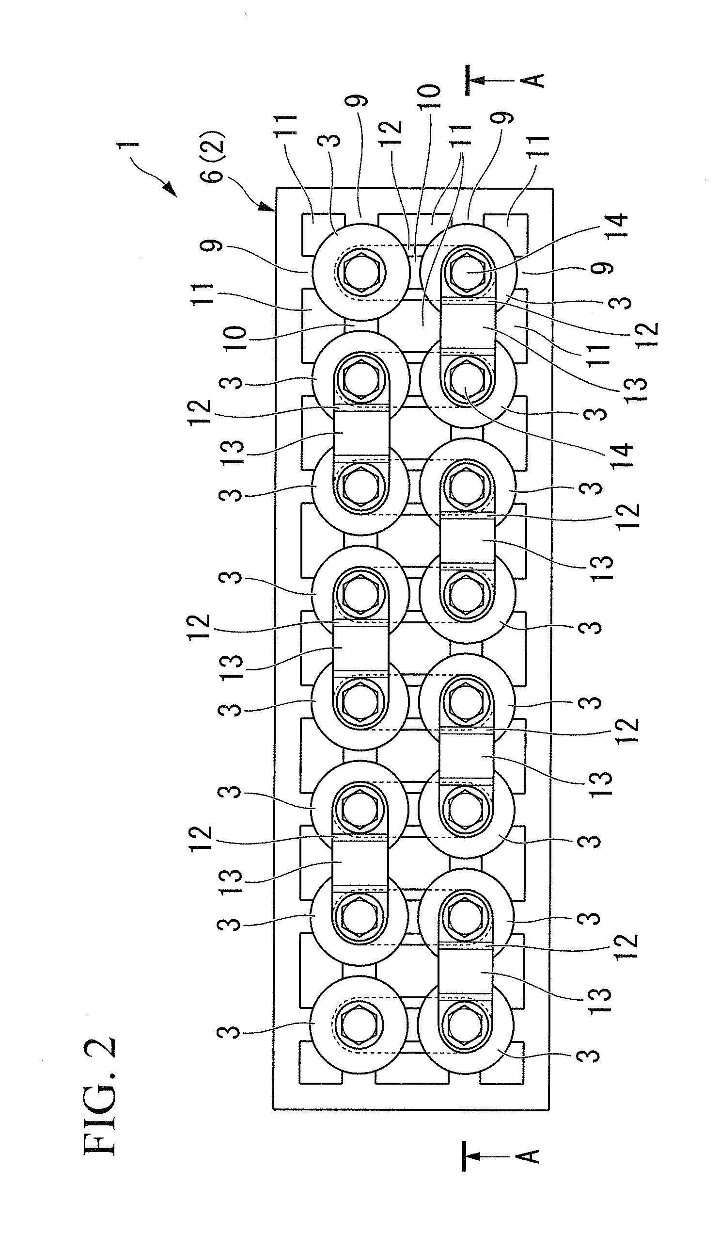
[0040]Initially, by referencing FIGS. 1 to 3, an explanation is given for this invention.

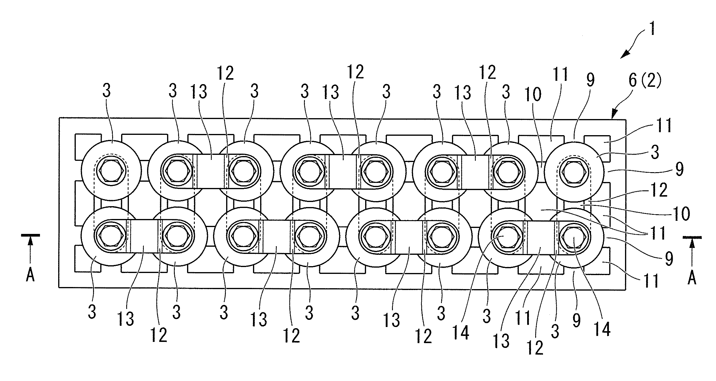
[0041]The battery container unit 1 of this embodiment is used as the driving electric source of electric cars which include hybrid cars. The plurality of battery modules 3 are provided in parallel and stored within the nearly rectangular parallelepiped metal enclosure 2. The module main body 4 is formed, as shown in FIG. 3, as cylinder-shaped in the battery module 3, and every one of the positive and negative electrode terminals is provided on both surfaces in the axial direction of this module main body 4. Moreover, in this specification, the battery module, in addition to being formed as a cylindrical shape by serially connecting a plurality of single batteries, includes also the case of a cylinder-shaped single battery unit.

[0042]The enclosure 2 includes the rectangular-shaped enclosure main body 6 with an opening provided at the ends of both opposing sides and a first cover 7 and a second co...

second embodiment

[0062]FIG. 6 shows this invention, having provided the first cooling medium flow path 19 on both sides in the axial direction of the plurality of battery modules 3 within the enclosure 2.

[0063]In the battery container unit 101, another feed port 15A and another discharge port 16A are provided on the side walls 8b of the second cover 8, as in the first cover 7. The plurality of bus bars 12 is provided so as to connect the electrode terminals 5 of the other end (referred to as second end) in the axial direction of the plurality of battery modules. FIG. 6 does not show the bus bars 12 of the second end, but in FIG. 2, bus bars 12 of the second end are shown by dotted lines. Another first cooling medium flow path 19 is formed in parallel and along these plurality of bus bars 12 of second ends. The discharge port 16A connects to the intake fan by the intake duct 17A. In addition, the protrusions 20A are formed on the ceiling wall 8a of the second cover 8, so as to face each bent convex p...

third embodiment

[0066]Moreover, this invention is not limited to the embodiments, and various design changes are possible without departing from the spirit and scope of the invention. For example, the previously described embodiments assume a flow accelerator by forming a protrusion 20 facing the bus bar on the first cover 7 or second cover 8. On the other hand, as shown in FIG. 7, in the battery container unit 201 of a third embodiment, flow accelerators may be formed by protrusions 30a and 30b which form a pair, by establishing on the first or second covers pairs of mutually facing protrusions 30a and 30b, having a predetermined gaps. In addition, for each embodiment described above, the intake fan 18 is connected to the discharge port 16 of the first cooling medium flow path 19, but instead, a pressure feed device of cooling air may be connected to the feed port 15 of the first cooling medium flow path 19.

[0067]Below, an explanation is given for still further embodiments of this invention, by re...


PUM

PropertyMeasurementUnit
cylindrical shapeaaaaaaaaaa
conductiveaaaaaaaaaa
flow speedaaaaaaaaaa

Abstract

A battery container unit including: an enclosure; and a plurality of battery modules of cylindrical shape, wherein each adjacent pair of the electrode terminals is serially connected by a conductive linking member, the plurality of battery modules are provided in matrix form within the enclosure by a support member, a first cooling medium flow path is provided which linearly flows a cooling medium along in parallel with the electrode terminals and the conductive linking members of the plurality of battery modules in a region within the enclosure near an end in the axial direction of the plurality of battery modules, and a second cooling medium flow path is provided in a gap along the axial direction of the battery modules, between adjacent battery modules within the enclosure, which flows the cooling medium toward the first cooling medium flow path.

Description

BACKGROUND OF THE INVENTION[0001]1. Field of the Invention[0002]This invention is related to a battery container unit.[0003]Priority is claimed on Japanese Patent Application No. 2007-223056, filed Aug. 29, 2007, and on Japanese Patent Application No. 2007-223057, filed Aug. 29, 2007, the contents of which are incorporated herein by reference.[0004]2. Description of Related Art[0005]As driving electrical sources for electric cars, in addition to parallel placement of a plurality of nearly cylindrical battery modules within an enclosure, battery container units are known that serially connect, by conductive linking members, internal adjacent battery modules.[0006]Every battery module generates heat from electrical charging and discharging for this kind of battery container unit. Because of the heat generated, it is necessary to efficiently cool the battery module in order to effectively use the capability of the battery module.[0007]Because of this requirement, feed ports and exhaust...

Claims


Application Information

Patent Timeline
Patent Type & Authority Applications(United States)
IPC IPC(8): H01M2/02H01M50/213H01M50/289H01M50/503H01M50/51
CPCH01M2/1072H01M2/206H01M10/5004H01M10/5016H01M10/5073H01M10/5038H01M10/5051H01M10/5067H01M10/503H01M10/625H01M10/6553H01M10/6563H01M10/652H01M10/643H01M10/6566H01M10/613Y02E60/10H01M50/213H01M50/51H01M50/503H01M50/289
Inventor NISHIDA, YOSHIKAZUTSUKAMOTO, KENJI
Owner HONDA MOTOR CO LTD
Learn More