

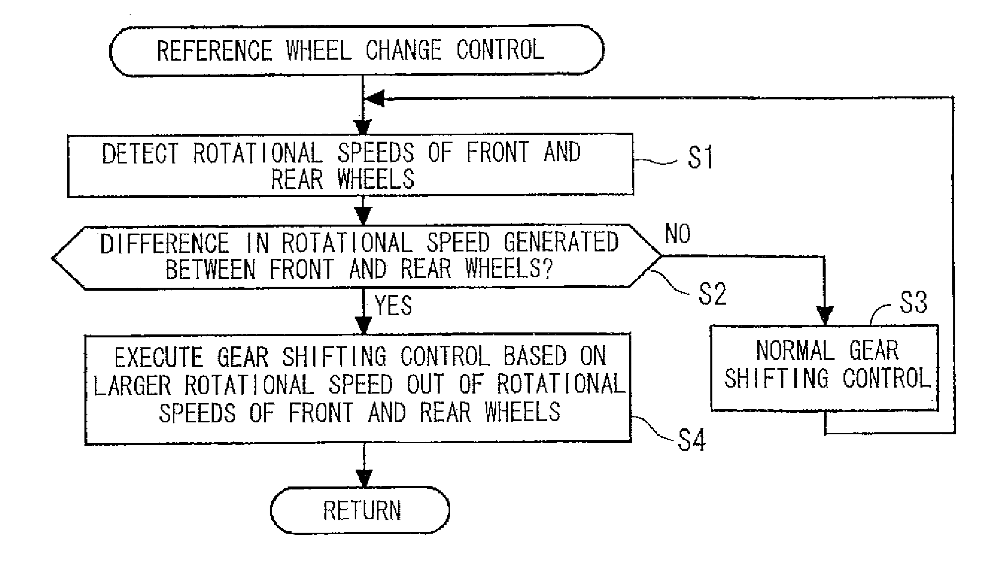
Automatic gear shifting control device of vehicle
a technology of automatic gear shifting and control device, which is applied in the direction of process and machine control, braking system, instruments, etc., can solve the problems of changing the method of detecting the difference in rotational speed between a driven wheel and a driving wheel, and affecting the operation of the braking system
- Summary
- Abstract
- Description
- Claims
- Application Information
AI Technical Summary
Benefits of technology
Problems solved by technology
Method used
Image


Examples
Embodiment Construction
[0026]The present invention will now be described in detail with reference to the accompanying drawings, wherein the same reference numerals will be used to identify the same or similar elements throughout the several views. It should be noted that the drawings should be viewed in the direction of orientation of the reference numerals.
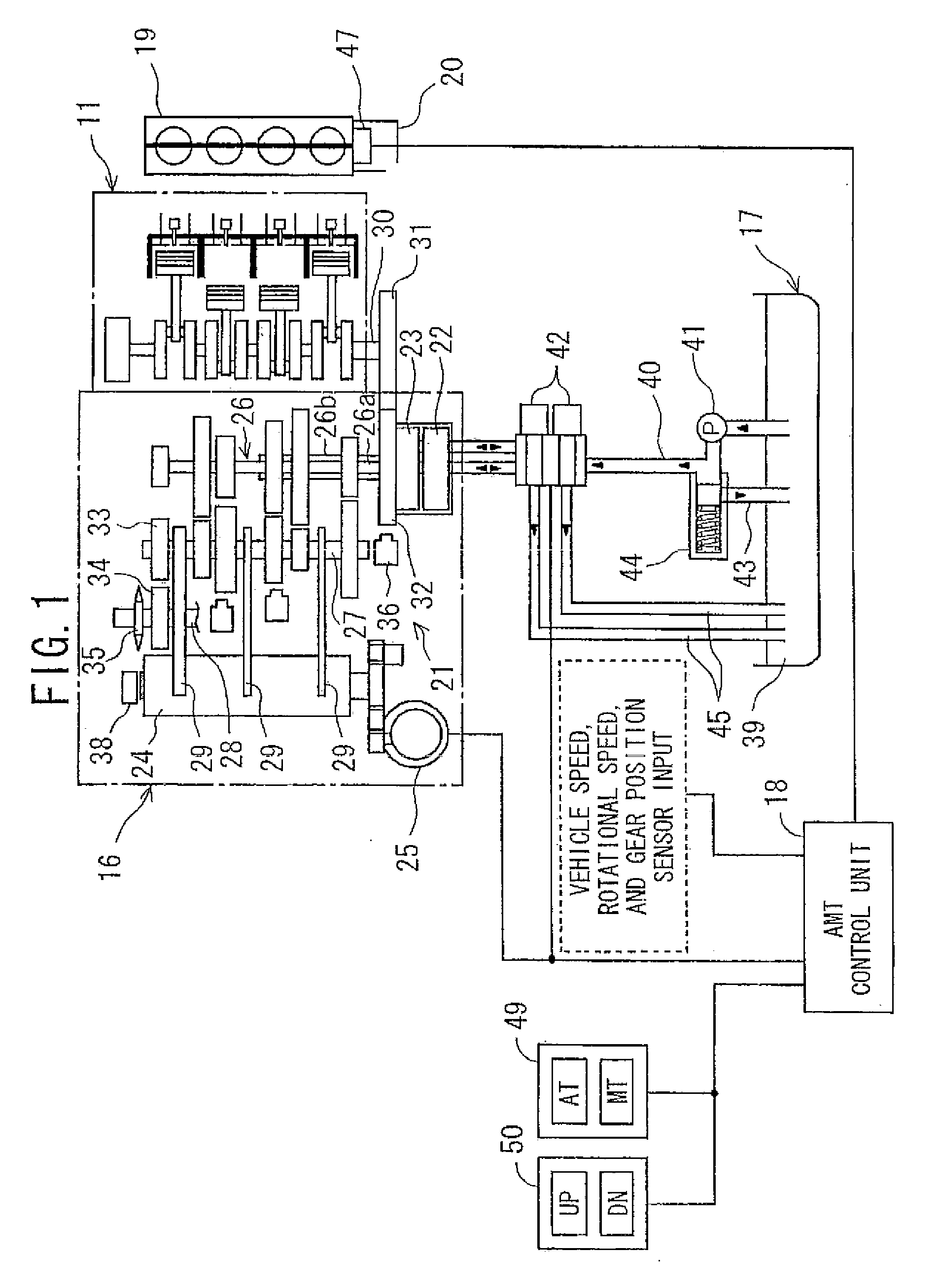
[0027]Hereinafter, a preferred embodiment of the present invention is explained in detail in conjunction with drawings. FIG. 1 is a system constitutional view of an automatic manual transmission (hereinafter, referred to as an AMT), which constitutes an automatic transmission applied to a motorcycle and devices around the AMT. The driving of the AMT 16 connected to an engine 11 is controlled by a clutch-use hydraulic device 17 and an AMT control unit 18. The engine 11 includes a throttle-by-wire (TBW) type throttle body 19. The throttle body 19 includes a motor 20 for opening and closing the throttle.
[0028]The AMT 16 includes a multi-stage transmission...
PUM
 Abstract
Description
Claims
Application Information