System and method of monitoring video data packet delivery

a video data packet and video data technology, applied in the field of monitoring video data packet delivery, can solve the problems of increasing the cost of continuous monitoring of video data packet traffic at each receiver, and increasing the cost of monitoring video data packet traffi

Inactive Publication Date: 2009-03-05
AT&T INTPROP I L P
View PDF41 Cites 110 Cited by
  • Summary
  • Abstract
  • Description
  • Claims
  • Application Information

AI Technical Summary

Problems solved by technology

Image quality may be affected by the loss of one or more packets of the stream of video data packets.
Packet losses can be caused by network congestion, packet errors, network device failures, other causes, or any combination thereof.
However, continual monitoring of video data packet traffic at each receiver can be prohibitively expensive and resource-intensive.
Performance data may also include failed requests for redelivery of video data packets.
Moving to 404, a potential problem may be identified based on a pattern of requests from the receiver.
For example, a potential problem may be identified based on a number of requests for video packet retransmission, an interval between consecutive requests, a ratio of requested packets, other metrics that may exceed a threshold value, or any combination thereof.
As an illustrative, non-limiting example, a video quality problem may be detected if a number of lost packets per unit time exceeds a threshold.
For example, an impending problem may be detected when one or more performance metrics exhibit a trend indicating a threshold value may be exceeded within a particular time period.
For example, a potential problem may be identified based on a number of requests for video packet retransmission, an interval between consecutive requests, a ratio of requested packets, other metrics that may individually or collectively be compared against the signatures stored at the knowledge base, or any combination thereof.
As an illustrative, non-limiting example, a video quality problem may be detected when the pattern of requests or the packet traffic, or both, match one or more signature files at the knowledge base within a certain degree of confidence.
Examples of signature files that may represent impending problems may include signature files reflecting an intermittent malfunction, a reduced capacity, or an upward trend in delivery failures.
For example, a technician dispatched to replace a malfunctioning network element may instead discover another cause of the video quality problem.
Problems such as failing network resources may be located and diagnosed, and corrective actions taken.
Additionally, the illustrations are merely representational and may not be drawn to scale.

Method used


Image

  • System and method of monitoring video data packet delivery
  • System and method of monitoring video data packet delivery
  • System and method of monitoring video data packet delivery

Examples


Embodiment Construction

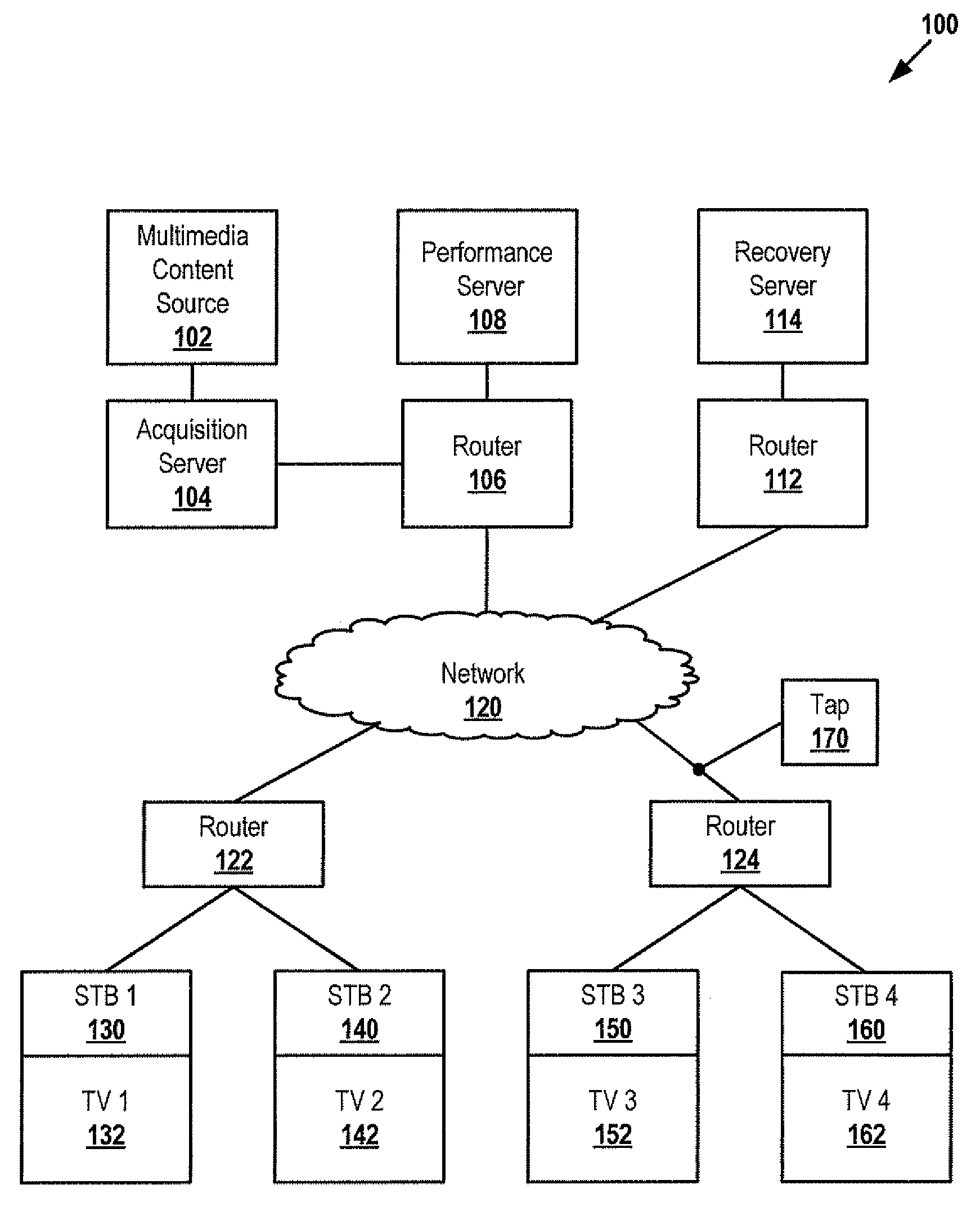
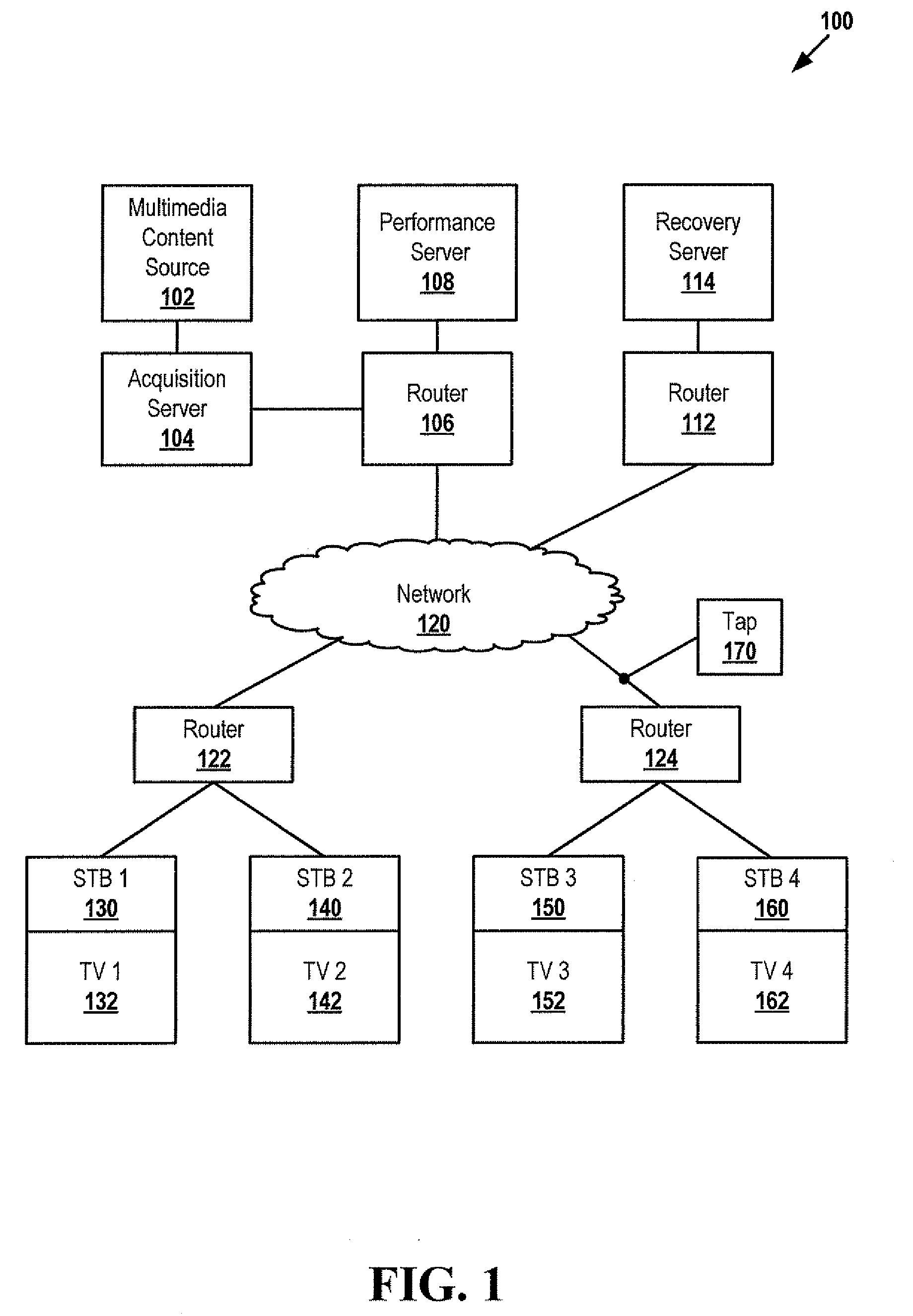
[0011]In a particular embodiment, a system is disclosed that includes a processor and a network interface accessible to the processor. The system also includes a memory accessible to the processor, the memory having instructions to cause the processor to execute a method. The method includes determining that a number of multicast video data packets not received at a multicast destination exceeds a threshold, the multicast video data packets sent from a video server to the multicast destination. The method includes querying a plurality of network devices for performance metrics corresponding to the multicast video data packets. The method includes identifying a delivery failure. The method further includes initiating a response to the delivery failure.

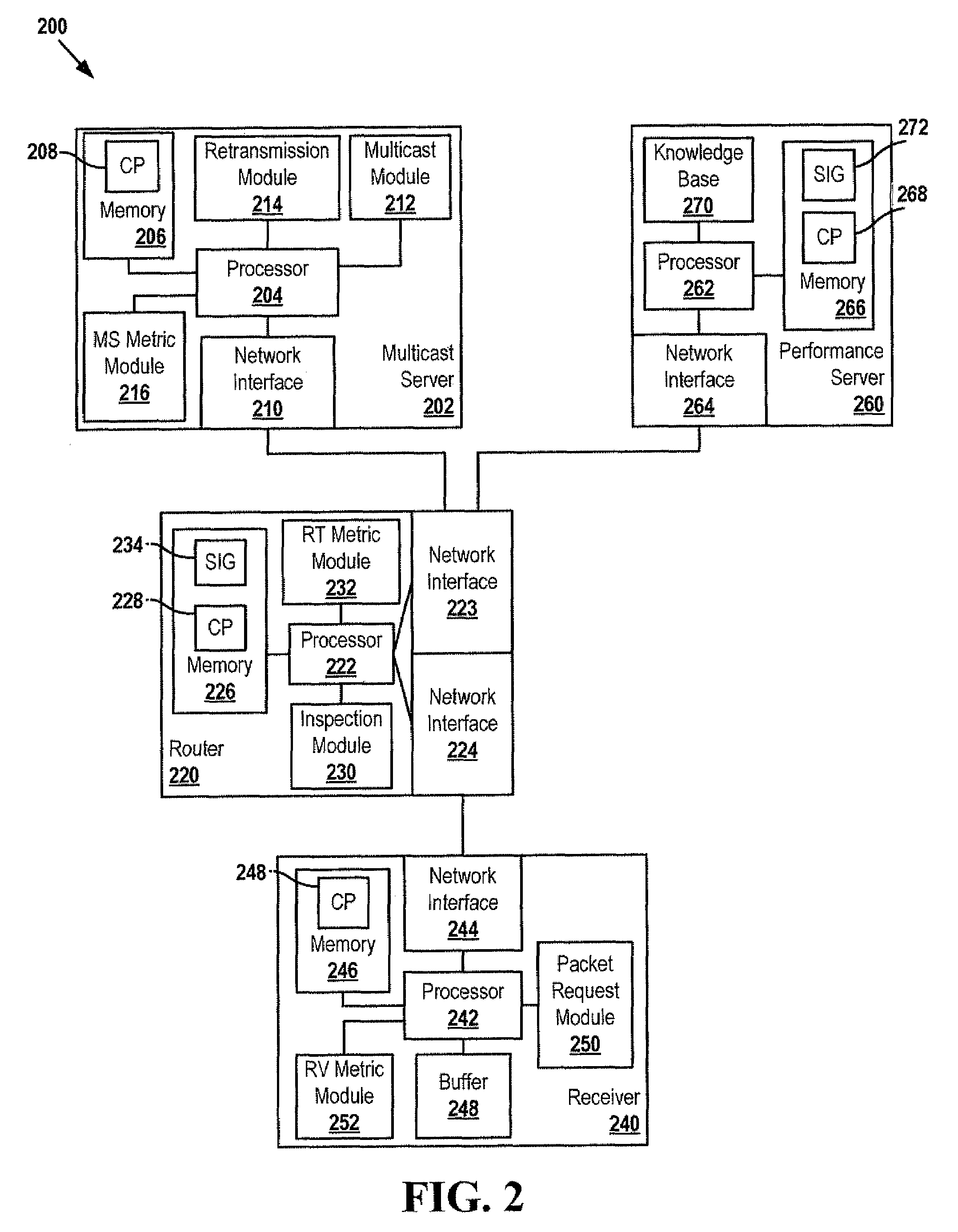
[0012]In another embodiment, a system is disclosed that includes a first network interface to communicate with a first network and a second network interface to communicate with a second network. The system also includes a processor cou...


PUM


Abstract

Systems and methods of monitoring packet delivery are disclosed. In an embodiment, a method is disclosed that includes querying multiple network devices for performance metrics corresponding to video data packets sent from a video server. The network devices may include multicast branching points between the video server and the destination. A delivery failure may be identified based on the performance metrics, and a response to the delivery failure may be initiated.

Description

FIELD OF THE DISCLOSURE[0001]The present disclosure is generally related to monitoring video data packet delivery.BACKGROUND[0002]Multimedia content can be delivered from a source to a receiver via a stream of video data packets. Image quality may be affected by the loss of one or more packets of the stream of video data packets. Packet losses can be caused by network congestion, packet errors, network device failures, other causes, or any combination thereof. Hence, there is a need for an improved system and method of monitoring video data packet delivery.BRIEF DESCRIPTION OF THE DRAWINGS[0003]FIG. 1 is a block diagram of a particular embodiment of a system to monitor video data packet delivery;[0004]FIG. 2 is a block diagram of a second particular embodiment of a system to monitor video data packet delivery;[0005]FIG. 3 is a block diagram of an Internet Protocol Television (IPTV) system;[0006]FIG. 4 is a flow chart of a particular embodiment of a method of monitoring video data pa...

Claims


Application Information

Patent Timeline
Patent Type & Authority Applications(United States)
IPC IPC(8): H04N7/173
CPCH04L12/1868H04N7/17318H04N21/64322H04N21/2404H04N21/258H04N21/2393
Inventor KWAN, DICKLI, ZHISAVOOR, RAGHVENDRASHRIKHANDE, KAPIL
Owner AT&T INTPROP I L P
Why Eureka
Try Eureka