
Starter with clutch coaxially disposed on output shaft of motor

a technology of coaxial disposed clutch and motor, which is applied in the direction of engine starters, machines/engines, power operated starters, etc., to achieve the effect of reducing the amount of grease leaking from the clutch, reducing the stiffness or rigidity of the clutch cover, and reducing elastic deformation

Inactive Publication Date: 2009-03-12
DENSO CORP
View PDF8 Cites 6 Cited by
  • Summary
  • Abstract
  • Description
  • Claims
  • Application Information

AI Technical Summary

Benefits of technology

[0014]An object of the present invention is to provide, with due consideration to the drawbacks of the conventional, a starter wherein elastic deformation of a clutch cover caused during the cranking of an engine is reduced.
[0017]However, because the distance between the front wall and the rotation axis is set to be smaller than the distance between the outer end of the clutch inner and the rotation axis, the stiffness or rigidity of the clutch cover is heightened. Further, the clutch washer and the clutch cover are overlapped with the clutch inner in the radial direction. Therefore, during the engagement of the pinion gear with the ring gear to crank the engine, when the clutch cover receives the pushing force caused by the forward movement through the clutch washer, the pushing force mainly acts as a shearing force on the clutch cover, and bending forces acting on the clutch cover are suppressed.
[0018]Accordingly, the clutch can greatly reduce elastic deformation generated in the clutch cover, so that the clutch can prevent the front wall of the clutch cover from being pushed and outstretched towards the outside (i.e., front side) of the clutch.
[0019]Further, the front wall of the clutch cover narrows the open space between the clutch cover and the neck of the shaft portion. Therefore, clutch grease packed in the clutch so as to surround the clutch roller hardly leaks from the clutch through the open space. Accordingly, an amount of grease leaking from the clutch can be considerably reduced, so that the size and weight of the starter can be minimized.

Problems solved by technology

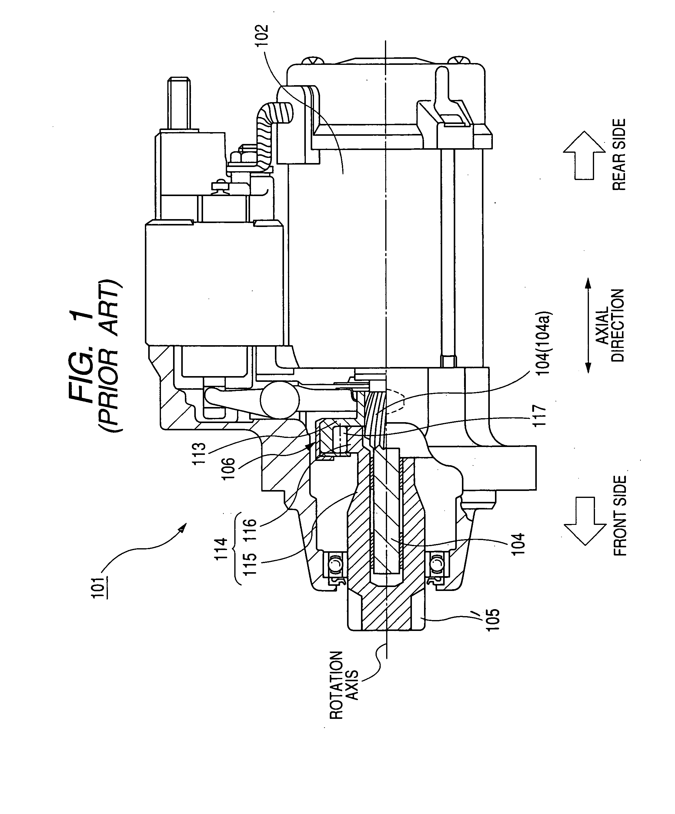
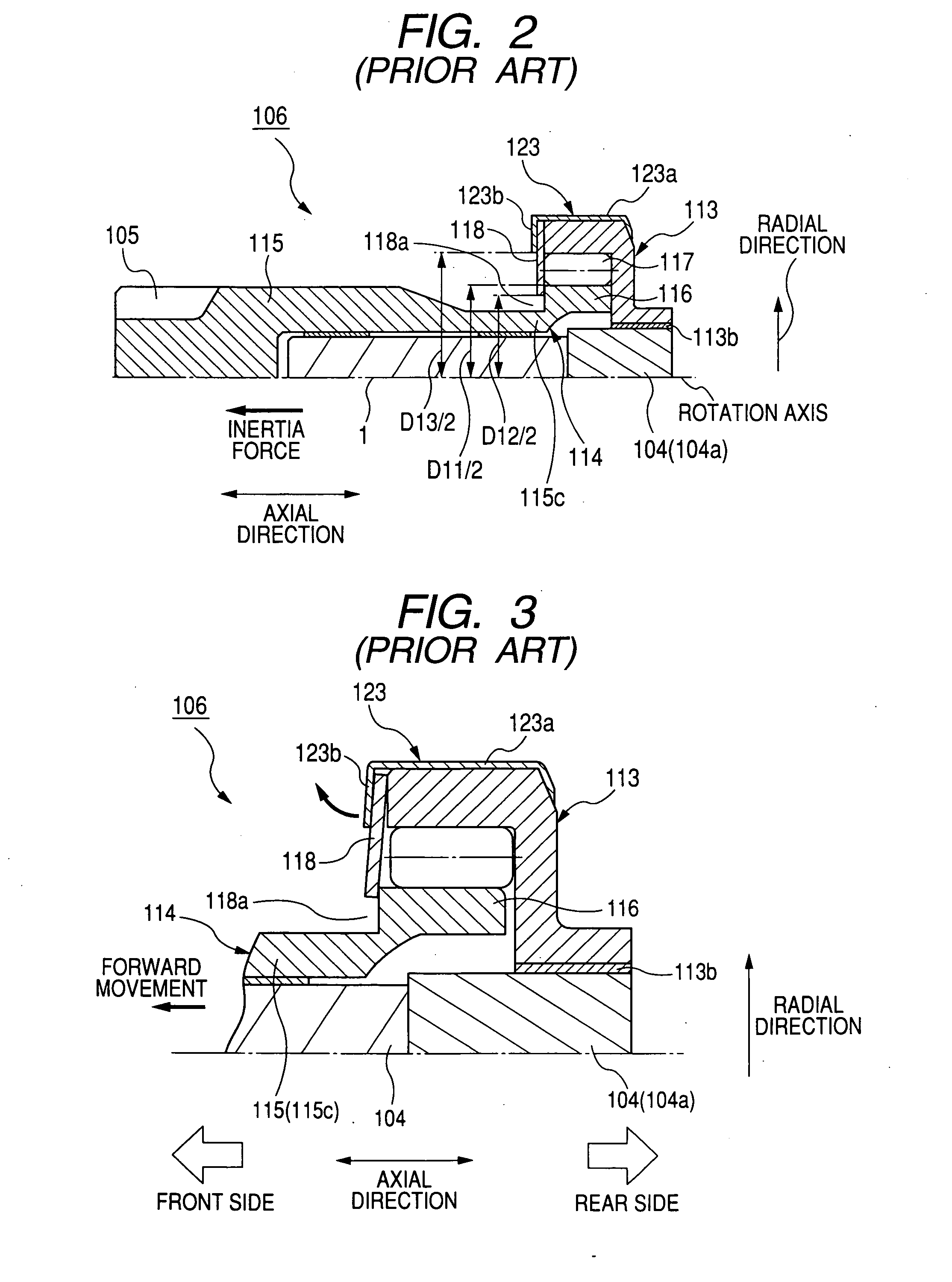
However, to reliably operate the clutch, a clutch 106 having no pinion stop undesirably becomes larger than a clutch having a pinion stop.

Method used


Image

  • Starter with clutch coaxially disposed on output shaft of motor
  • Starter with clutch coaxially disposed on output shaft of motor
  • Starter with clutch coaxially disposed on output shaft of motor

Examples


embodiment

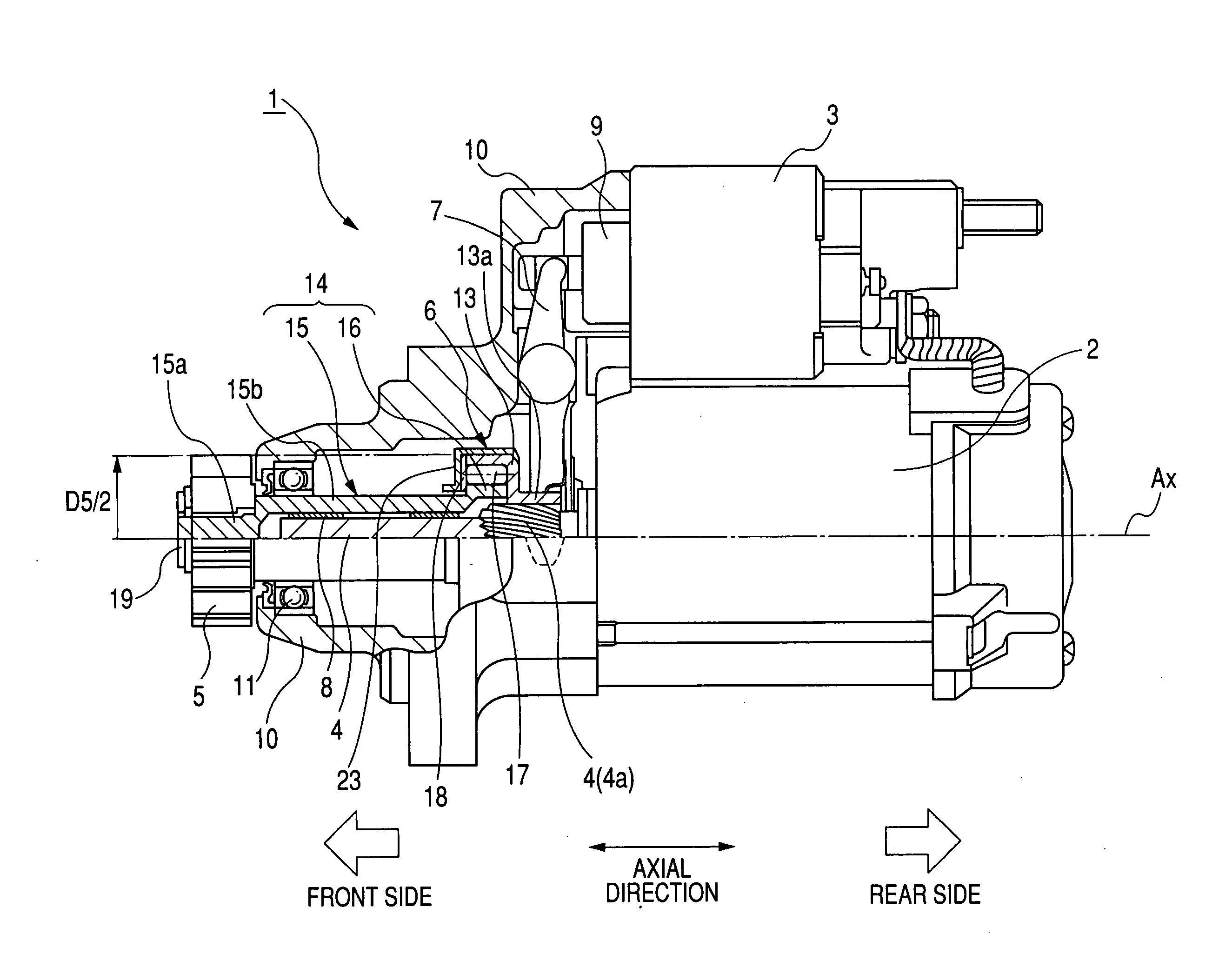
[0027]FIG. 4 is a side elevational view, partly in cross section, of a starter according to this embodiment, while FIG. 5 is an enlarged sectional view of a clutch disposed in the starter.

[0028]As shown in FIG. 4 and FIG. 5, a starter 1 for cranking an internal combustion engine is, for example, disposed on a vehicle. The starter 1 has a motor 2 for generating a rotational force, an electromagnetic switch 3 for electrically connecting the motor 2 to a battery (not shown) and electrically disconnecting the motor 2 from the battery, an output shaft 4 fixedly connected with the motor 2 so as to be rotated on its own axis, a one-way clutch 6 coaxially coupled with both the output shaft 4 and a pinion gear 5 to transmit the rotational force from the output shaft 4 to the pinion gear 5, and a shift lever 7. The output shaft 4, the clutch 6 and the pinion gear 5 are rotatable on an axis Ax of rotation.

[0029]The motor 2 is, for example, formed of a well-known direct current (AC) motor havin...


PUM


Abstract

A starter has a clutch coaxially disposed on an output shaft of a motor. The clutch has a clutch outer, an inner member having a clutch inner disposed on an inner side of the outer and a shaft portion disposed on a front side of the inner, a roller disposed between the outer and inner, a clutch cover attached to an outer surface of the outer and extending toward the shaft portion, and a clutch washer disposed on a front surface of the inner between the cover and inner. The distance between the cover and the rotation axis of the clutch is smaller than the distance between the outer end of the inner and the rotation axis. The rotation force of the motor is received in the outer and is transmitted to an engine through the roller and inner member to crank the engine.

Description

CROSS-REFERENCE TO RELATED APPLICATION[0001]This application is based upon and claims the benefit of priority of the prior Japanese Patent Application 2007-236396 filed on Sep. 12, 2007, so that the contents of which are incorporated herein by reference.BACKGROUND OF THE INVENTION[0002]1. Field of the Invention[0003]The present invention relates generally to a starter for an internal combustion engine, and more particularly to the starter with a clutch coaxially disposed on an output shaft of a motor.[0004]2. Description of Related Art[0005]A starter has been used to crank an internal combustion engine mounted on a vehicle by transmitting a rotational force of a motor to the engine. This starter is, for example, disclosed in Published Japanese Patent First Publication No. 2007-16720. In this starter, a one-way clutch is coaxially disposed on an output shaft of a motor. When a pinion gear coupled with a shaft portion of the clutch is engaged with a ring gear of an engine, the pinion ...

Claims


Application Information

Patent Timeline
Patent Type & Authority Applications(United States)
IPC IPC(8): F02N15/00
CPCY10T74/13F02N15/023
Inventor HIRABAYASHI, TAKASHI
Owner DENSO CORP
Learn More