Electyrophoretic display and method for driving the same

a technology of electrophoretic display and electrophoretic display, which is applied in the direction of instruments, static indicating devices, etc., can solve the problems of deteriorating display performance and non-uniform display size of the entire display area between neighboring pixels, and achieve the effect of improving image display performance and uniform size of the real imag

Active Publication Date: 2009-03-12
HYDIS TECH
View PDF9 Cites 17 Cited by
  • Summary
  • Abstract
  • Description
  • Claims
  • Application Information

AI Technical Summary

Benefits of technology

[0011]According to the present invention a method is provided for driving an electrophoretic display that can improve image display performance by symmetricall

Problems solved by technology

Accordingly, the entire display size between neighboring pixels becomes non-uniform.
Further, if the image display voltages are repeatedly applied to the electrophoretic particles to

Method used


Image

  • Electyrophoretic display and method for driving the same
  • Electyrophoretic display and method for driving the same
  • Electyrophoretic display and method for driving the same

Examples


first embodiment

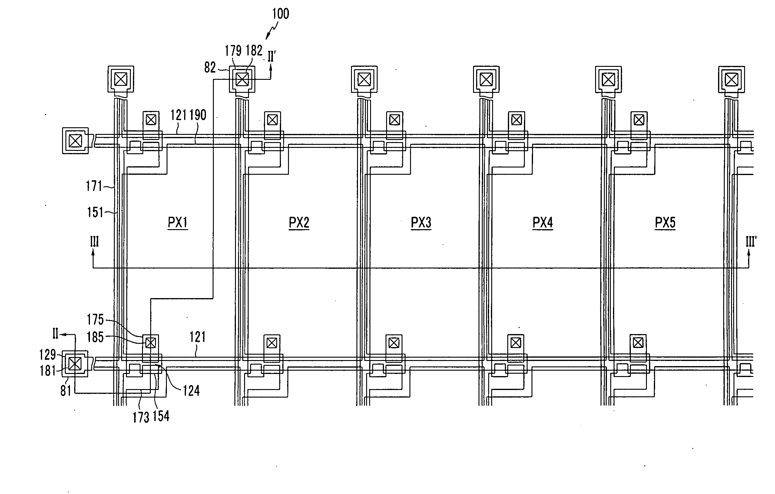
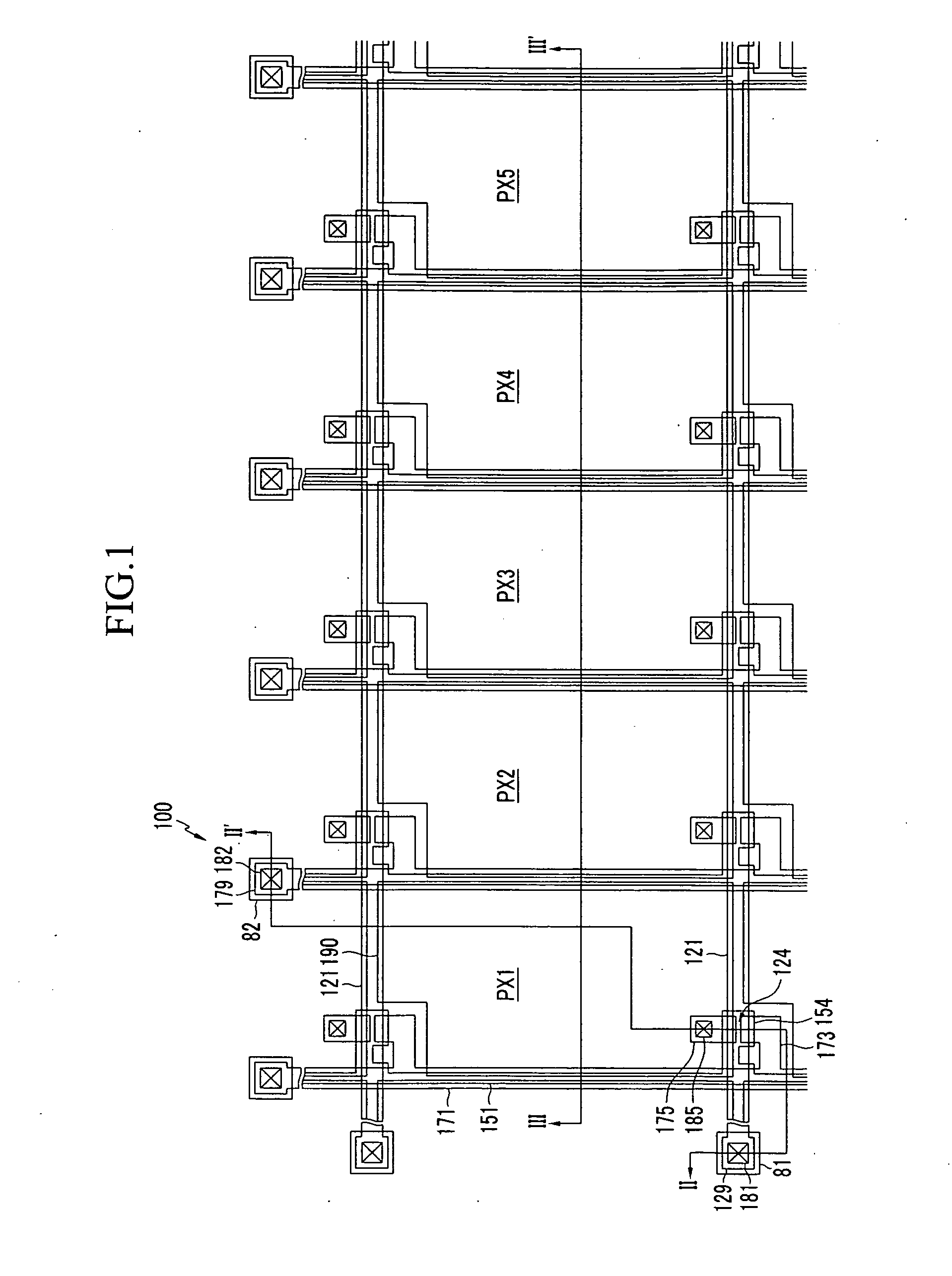
[0142]In the driving method of the electrophoretic display according to the second exemplary embodiment of the present invention, an image display compensation voltage is firstly applied to each pixel PX1, PX2, PX3, PX4, and PX5 before the application of a reset voltage. The subsequent voltage application steps are the same as those in the driving method of the electrophoretic display of the present invention.

second embodiment

[0143]In this second embodiment, when a driving end signal is applied to the electrophoretic display in the step of applying the image display voltage, the driving may be finished after the completion of the step of applying the image display voltage. Next, when a driving start signal is applied to the electrophoretic display, the reset compensation voltage is applied after the step of applying the image display compensation voltage that is reversed with respect to the image display voltage that is applied before the driving end.

[0144]As above described, each pixel PX1, PX2, PX3, PX4, and PX5 displays the images of five grays from the 0 gray to the fourth gray that are different images in the driving method of the electrophoretic display according to the various exemplary embodiments of the present invention, but more various images of black and white may be displayed by subdividing the application time of the image display voltage and the image display compensation voltage.

[0145]Fu...


PUM


Abstract

Disclosed is an electrophoretic display and a method for driving the electrophoretic display. The method for driving the electrophoretic display, which includes a first electrode, a second electrode, and an electrophoretic layer including electrophoretic particles disposed in a plurality of pixels receiving the voltage for driving from the first electrode and the second electrode and provided between the first electrode and the second electrode includes applying a reset voltage to the pixels, applying a reset compensation voltage including reversed polarity to the reset voltage to the pixels, applying an image display voltage including the same or different polarity during a predetermined time between the neighboring pixels, and applying an image display compensation voltage including reversed polarity to the image display voltage to the pixels during a predetermined time. The foregoing method provides a potential distribution which is symmetrical in the boundary region between the neighboring pixels such that the display size of the real image of each of the pixels is uniform and an afterimage may be prevented, thereby improving the display performance.

Description

CROSS-REFERENCE TO RELATED APPLICATION[0001]This application claims priority to and the benefit of Korean Patent Application No. 10-2007-0090530 filed in the Korean Intellectual Property Office on Sep. 6, 2007, the entire contents of which are incorporated herein by reference.BACKGROUND OF THE INVENTION[0002](a) Field of the Invention[0003]The present invention relates to a method for driving an electrophoretic display. More particularly, the present invention relates to a method for driving an electrophoretic display to provide the display of uniform images in each pixel in the electrophoretic display.[0004](b) Description of the Related Art[0005]Recently, flat panel displays including an electrophoretic display (EPD) and a liquid crystal display (LCD) have been developed as substitutes for a cathode ray tube (CRT) display.[0006]The electrophoretic display includes a thin film transistor array panel having a plurality of pixel electrodes, a common electrode panel having a common el...

Claims


Application Information

Patent Timeline
IPC IPC(8): G09G3/34
CPCG09G3/344G09G2300/08G09G2310/0251G09G2320/0257G09G2310/068G09G2320/0209G09G2320/0233G09G2310/063
Inventor HONG, SUNG-JINLEE, II-PYUNGPARK, JAE-BYUNGLEE, YONG-WOOYANG, SUNG-HOON
Owner HYDIS TECH
Why Eureka
Try Eureka