Projection type image display device

Inactive Publication Date: 2009-03-12
PANASONIC CORP
View PDF16 Cites 13 Cited by
  • Summary
  • Abstract
  • Description
  • Claims
  • Application Information

AI Technical Summary

Benefits of technology

[0014]According to the first to fourth configurations of the projection type image display device of the present invention, light from plane-emission light source having a wide emission angle can be collected efficiently and taken into the image display apparatus.
[0015]Also, in the preferable example in which the light emitting portion of the light source is inclined toward the surface vertex of the reflection surface of the reflector with reference to the center axis of rotation of the reflection surface of the reflector, the amount of light that is emitted directly toward the exit surface of the reflector is reduced, resulting in an improvement of light use efficiency.
[0016]Also, in the preferable example in which the center axis of rotation of the reflection surface of the reflector is inclined with respect to a system axis that is an optical axis common to optical parts excluding the reflector and the light source so that the

Problems solved by technology

However, in the case of the high-pressure mercury lamp, ultraviolet light or infrared light is generated in addition to desired visible light, leading to considerably high temperatures in a portion surr

Method used


Image

  • Projection type image display device
  • Projection type image display device
  • Projection type image display device

Examples


first embodiment

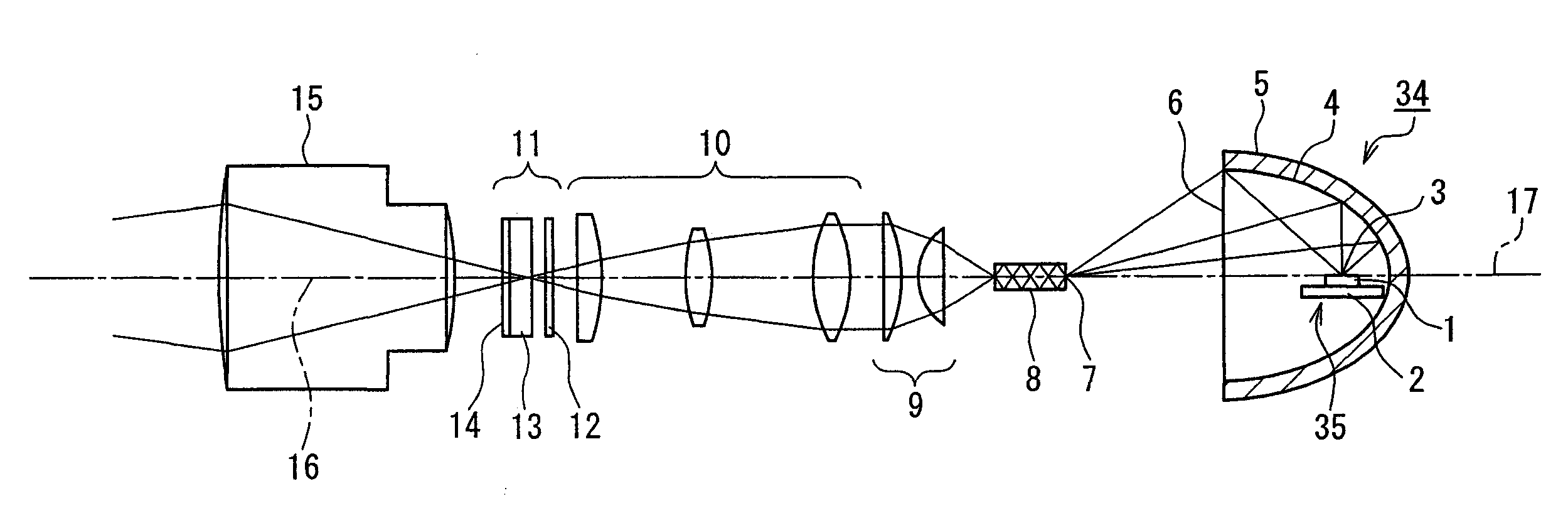
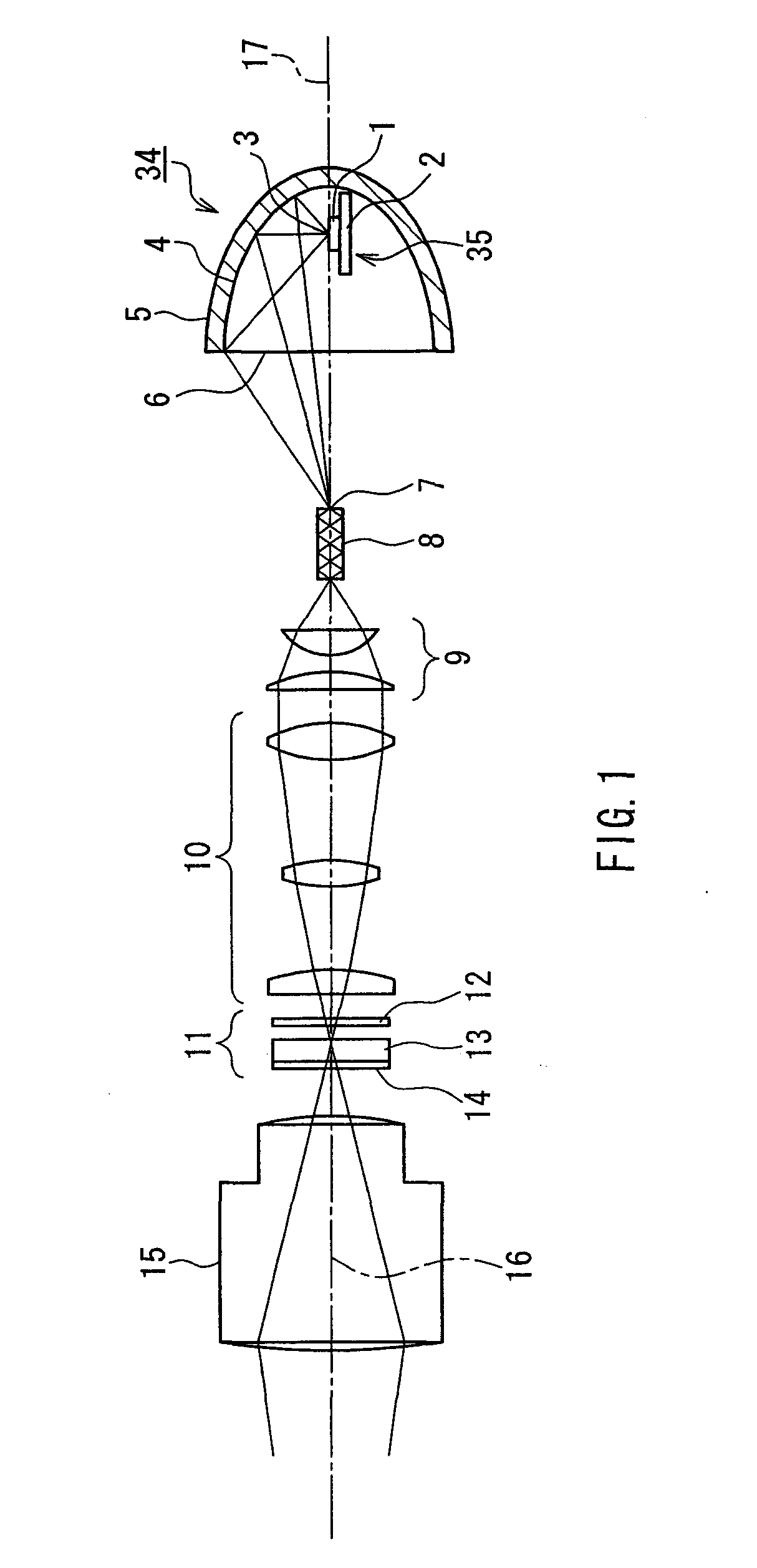
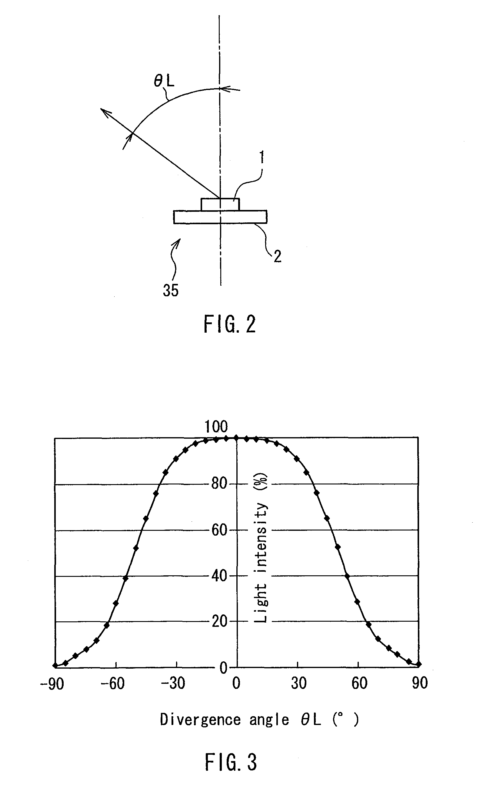
[0032]FIG. 1 is a configuration diagram showing a projection type image display device according to a first embodiment of the present invention. FIG. 2 is a side view showing a light source used in the projection type image display device.

[0033]As shown in FIG. 1, the projection type image display device of this embodiment is configured by sequentially arranging an illumination unit 34, a rod integrator 8, a condenser lens 9, a relay optical system 10, a light modulator 11 as a light modulating device, and a projection lens 15 as a projection optical system.

[0034]The illumination unit 34 includes a light source 35 and a reflector 5 having an ellipsoidal reflection surface 4 as an inner surface thereof. The light source 35, which is a solid-state light emitting source, includes a substrate 2 connected to a power supply source (not shown), and a light emitting portion 1 that is mounted on the substrate 2 and is substantially planar. The ellipsoidal reflection surface 4 of the reflecto...

second embodiment

[0049]FIG. 7 is a configuration diagram showing a projection type image display device according to a second embodiment of the present invention.

[0050]As shown in FIG. 7, the projection type image display device of this embodiment is configured by sequentially arranging an illumination unit 36, a condenser lens 22, a rod integrator 8, a relay optical system 24, a light modulator 11 as a light modulating device, and a projection lens 15 as a projection optical system. In FIG. 7, numeral 16 indicates a system axis that is an optical axis common to optical parts including the condenser lens 22, the rod integrator 8, the relay optical system 24, the light modulator 11, and the projection lens 15 other than the illumination unit 36. Note that the rod integrator 8, the light modulator 11, and the projection lens 15 are the same as those described in the first embodiment and will not be described in detail.

[0051]The illumination unit 36 includes a light source 35 and a reflector 20 having ...

third embodiment

[0061]FIG. 8 is a configuration diagram showing a projection type image display device according to a third embodiment of the present invention. As shown in FIG. 8, the projection type image display device of this embodiment is configured by sequentially arranging an illumination unit 36, a lens-array integrator 26, a field lens 30, a light modulator 11 as a light modulating device, and a projection lens 15 as a projection optical system. In FIG. 8, numeral 16 indicates a system axis that is an optical axis common to optical parts including the lens-array integrator 26, the field lens 30, the light modulator 11, and the projection lens 15 other than the illumination unit 36. Note that the illumination unit 36 is the same as that of the second embodiment and will not be described in detail. Also, the light modulator 11 and the projection lens 15 are the same as those of the first embodiment and will not be described in detail.

[0062]The lens-array integrator 26, which is provided in f...


PUM


Abstract

A projection type image display device includes a reflector 5 having an ellipsoidal reflection surface 4 as an inner surface thereof, a light source 35 in which at least a light emitting portion 1 is substantially planar, a light distribution thereof is within ±90° with respect to a normal line perpendicular to the plane, and the light emitting portion 1 is located optically at a first focus 3 of the spheroid forming the ellipsoidal reflection surface 4 of the reflector 5, a rod integrator 8 having an entrance opening portion in which a second focus 7 of the spheroid forming the ellipsoidal reflection surface 4 of the reflector 5 is located at the entrance opening portion thereof, a light modulator 11 capable of modulating an output of transmission light in accordance with an external signal, a relay optical system 10 for transferring an image of an exit opening portion of the rod integrator 8 onto the light modulator 11, and a projection lens 15 for enlarging and projecting the image on the light modulator 11 onto a screen. Thereby, the light uptake rate to the image display apparatus of the light source having a flat light emitting surface and for emitting light in one direction of the surface can be improved so as to maximize the brightness.

Description

TECHNICAL FIELD[0001]The present invention relates to a projection type image display device including a light source having a flat light emitting surface.BACKGROUND ART[0002]Conventionally, in an illumination unit of a projection type image display device, generally, a high-pressure mercury lamp is employed as a light source (see, for example, Patent Document 1). This is mainly because its light emitting portion is a gap between electrodes and is considerably small (mainstream gap length: 1 to 1.5 mm), so that light easily is collected optically to the image display apparatus, and also, the light source itself has excellent light emission efficiency. However, in the case of the high-pressure mercury lamp, ultraviolet light or infrared light is generated in addition to desired visible light, leading to considerably high temperatures in a portion surrounding the light source. Also, the life span is generally about 2000 hours (10000 hours for a long-life type), so that replacement is ...

Claims


Application Information

Patent Timeline
IPC IPC(8): G03B21/28
CPCH04N9/315G03B21/2013G03B21/2066H04N9/3197
Inventor YAMAGISHI, SHIGEKAZUSHIMAOKA, YUSAKUFUSHIMI, YOSHIMASAWADA, MITSUHIRO
Owner PANASONIC CORP
Why Eureka
Try Eureka