
Method and apparatus for enhancing the accuracy of CRDS measurements

a technology of spectroscopic measurement and enhancing accuracy, which is applied in the field of enhancing the accuracy of spectroscopic measurement, can solve the problems of spectral fitting being problematic and increasing the uncertainty of measured loss, so as to reduce the amplitude of the artifact, improve the estimate of the actual loss, and reduce the effect of artifa

Active Publication Date: 2009-03-12
PICARRO
View PDF7 Cites 4 Cited by
  • Summary
  • Abstract
  • Description
  • Claims
  • Application Information

AI Technical Summary

Benefits of technology

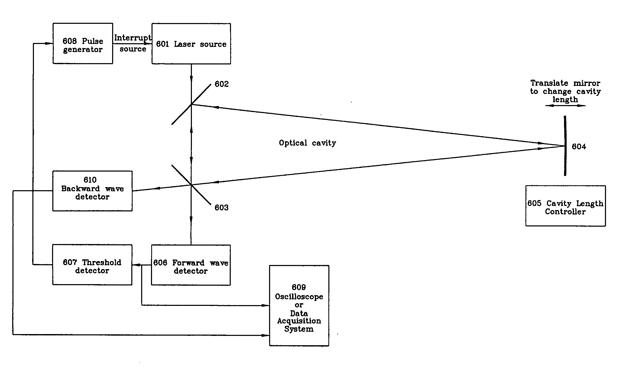
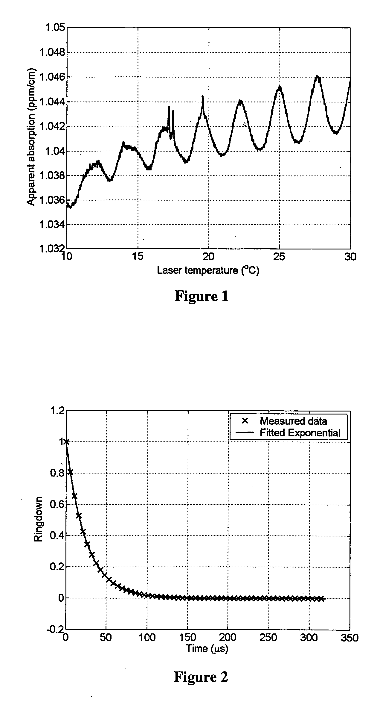
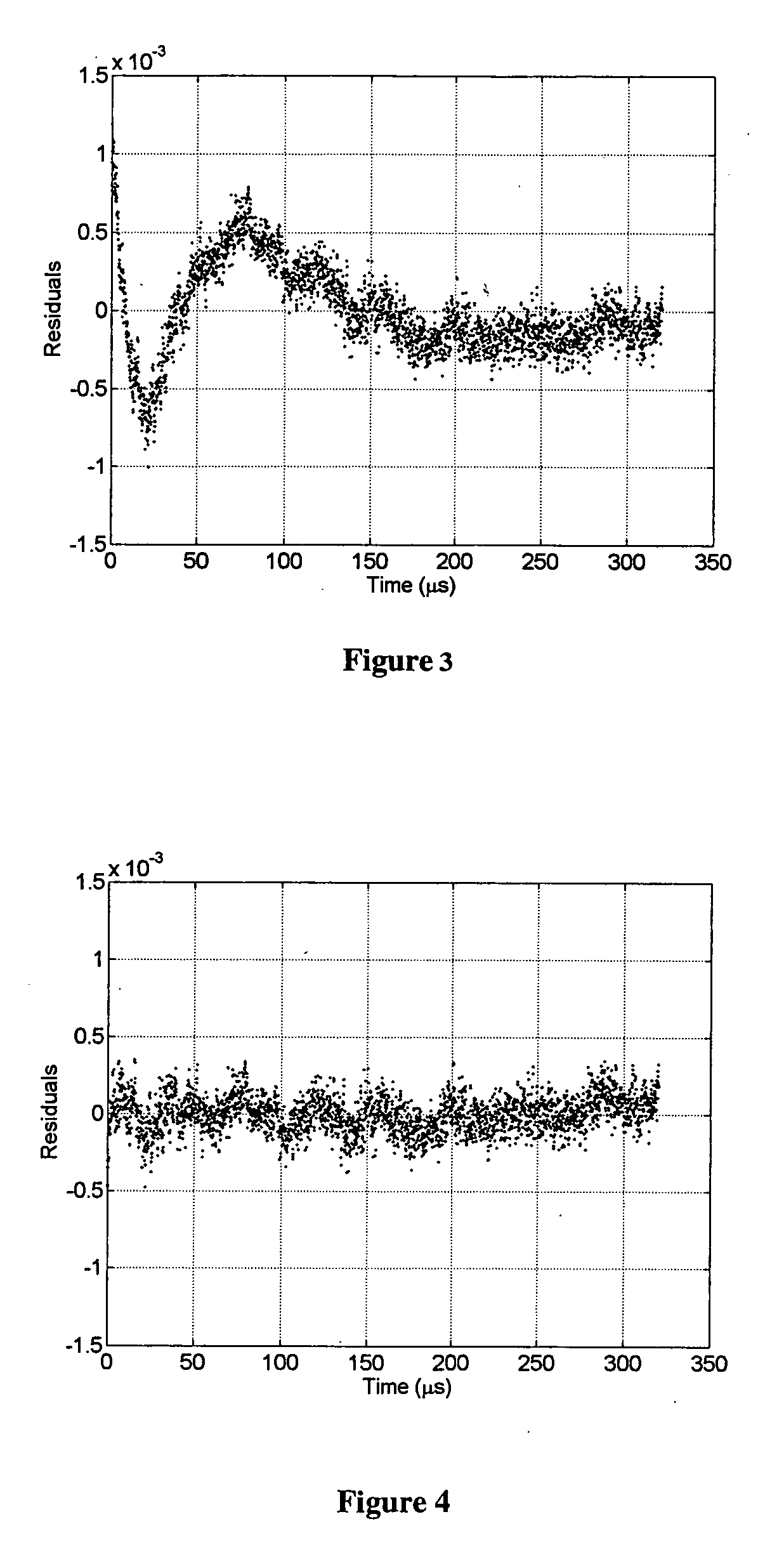
[0005]A first aspect of the invention consists of a novel algorithm for the processing of ring-down data that significantly reduces the amplitude of the artifact, and thereby gives a better estimate of the actual loss. Although the algorithm succeeds in reducing the artifact, it does so at the cost of increasing somewhat the uncertainty in the measured loss. It is therefore preferable to construct cavities for which the artifact is as small as possible. I have identified the primary cause of the artifact to be the presence of an unwanted backwards-traveling wave that counter-propagates within the ringdown cavity. Scattering due to small imperfections at the cavity mirrors produces this wave and its intensity may be minimized by adjustment of the mirror positions during cavity construction. A second aspect of the invention consists of an apparatus for measuring the backscattered wave within a cavity to allow such cavity mirror adjustments to be made.

Problems solved by technology

Such a variation in the baseline can hide small peaks and make spectral fitting problematic.
I have determined that there is no physical mechanism for producing such a variation in absorption, and that it is an artifact caused by the inappropriate use of exponential fitting for determining the loss.
Although the algorithm succeeds in reducing the artifact, it does so at the cost of increasing somewhat the uncertainty in the measured loss.

Method used


Image

  • Method and apparatus for enhancing the accuracy of CRDS measurements
  • Method and apparatus for enhancing the accuracy of CRDS measurements
  • Method and apparatus for enhancing the accuracy of CRDS measurements

Examples


Embodiment Construction

[0012]When a cavity is filled so that exactly one mode is excited, the intensity of the light in the cavity decays exponentially after the excitation is ended. When a ring cavity (e.g., three or four mirror) is used, a mode corresponds to a wave with a specific polarization and spatial profile that propagates in one direction around the cavity. In a cavity ring-down spectrometer, the light entering the cavity is aligned and shaped so as to excite only a single cavity mode. The common practice of fitting the ring-down waveform by an exponential in order to determine the time constant and the loss within the cavity is based on the assumption that only a single mode has been excited.

[0013]By carefully examining the ring-down waveform collected at the output of the cavity when the input light to the cavity is turned off, I have determined that this assumption is often invalid. The input light couples most strongly to a mode that propagates in one direction around the cavity (the “forwar...


PUM

PropertyMeasurementUnit
ringdown time constantaaaaaaaaaa
ringdown timeaaaaaaaaaa
reflectivityaaaaaaaaaa

Abstract

A method and apparatus for enhancing the accuracy of spectroscopic measurements using a cavity ringdown spectrometer (CRDS) is provided. A first aspect of the invention consists of a novel algorithm for the processing of ring-down data that significantly reduces the amplitude of an exponential fitting artifact, and thereby gives a better estimate of the actual loss. The primary cause of the artifact is the presence of an unwanted backwards-traveling wave that counter-propagates within the ringdown cavity. Scattering due to small imperfections at the cavity mirrors produces this wave and its intensity may be minimized by adjustment of the mirror positions during cavity construction. A second aspect of the invention consists of an apparatus for measuring the backscattered wave within a cavity to allow such cavity mirror adjustments to be made.

Description

FIELD OF THE INVENTION[0001]This invention relates to a method and apparatus for enhancing the accuracy of spectroscopic measurements using a cavity ringdown spectrometer (CRDS).BACKGROUND OF THE INVENTION[0002]CRDS is known to be a highly accurate spectroscopic technique. In the most advantageous implementation of CRDS, a three or four mirror ring cavity is used. The cavity mirrors must have very high reflectivity and low loss in order to achieve a high cavity finesse.[0003]Light is coupled into the cavity to excite a forward-propagating wave that decays when the light source is interrupted. If one assumes that light only travels in one direction around the cavity, the intensity of the light exiting the cavity after the light source is interrupted decays exponentially with time. The time constant (τ) of the exponential decay gives an absolute measurement of the total loss suffered by the light as it traverses the cavity. By measuring the variation in the time constant for a number ...

Claims


Application Information

Patent Timeline
Patent Type & Authority Applications(United States)
IPC IPC(8): G01N21/61
CPCG01J3/28G01N2021/399G01N21/39G01J3/42
Inventor TAN, SZE
Owner PICARRO
Learn More