Fastening structure and rotary vacuum pump

a technology of fastening structure and vacuum pump, which is applied in the direction of screws, washing machines, ways, etc., can solve the problems of rotors being subjected to a large centrifugal force, large impact force applied to stators, and rotors being susceptible to breakage, so as to reduce impact stress, prevent damage, and reduce impact stress

Inactive Publication Date: 2009-03-12
SHIMADZU CORP
View PDF6 Cites 11 Cited by
  • Summary
  • Abstract
  • Description
  • Claims
  • Application Information

AI Technical Summary

Benefits of technology

[0008]In view of the above circumstances, it is an object of the present invention to provide a fastening structure capable of preventing breakage of a bolt for fastening a first member to a second member, and damages in the first and second members.
[0009]It is another object of the present invention to provide a rotary vacuum pump capable of preventing damages in the rotary vacuum pump itself and a target unit fastened to a gas inlet flange thereof.
[0010]In order to achieve the above objects, according to a first aspect of the present invention, there is provided a fastening structure for fastening a first member and a second member by a bolt. The fastening structure comprises a cushioning member which is made of a porous metal material, and disposed to absorb kinetic energy to be transmitted from either one of the first and second members to the other member, while reducing an impact stress to be applied to the bolt.
[0014]According to the third aspect of the present invention, there is provided a rotary vacuum pump comprising: a pump casing having a gas inlet flange formed to be fastened to a target unit; a rotor provided with rotation-side gas discharge means and disposed inside the pump casing in such a manner as to be rotationally driven at a high speed; a stationary-side gas discharge means disposed inside the pump casing to produce a gas-discharging function in cooperation with the rotation-side gas discharge means; and a cushioning member which is made of a porous metal material, and disposed between the stationary-side gas discharge means and the pump casing to absorb kinetic energy to be transmitted from the stationary-side gas discharge means to the pump casing, while reducing an impact stress to be applied to the pump casing, when the rotation-side gas discharge means is damaged.
[0015]In the fastening structure of the present invention, the cushioning member made of a porous metal material is disposed to absorb kinetic energy to be transmitted from either one of the first and second member to the other member through the bolt, while reducing an impact stress to be applied to the bolt. This makes it possible to prevent breakage of the bolt, and damages in the first and second members.
[0016]In the rotary vacuum pump set forth in the second or third aspect of the present invention, the cushioning member makes it possible to prevent damages in the rotary vacuum pump itself and the target unit.

Problems solved by technology

Thus, if an abnormal disturbance acts on the rotor, the rotor is likely to be brought into contact with a stator (e.g., the threaded stator), and thereby a large impact force is applied to the stator.
Moreover, during a high-speed rotation of the rotor, the rotor is constantly subjected to a large centrifugal force.
Thus, if the rotor is brought into contact with the stator, or continuously operated under harsh conditions beyond assumptions in a design stage thereof, the rotor is likely to be broken.
In this case, due to a larger impact force applied to the stator, a large shearing force will be undesirably applied to a bolt which fastens a pump casing to a body of a target unit that will be subjected to a vacuum.
Although this conventional technique is designed to allow the bolt to be brought into contact with a lateral region of an inner peripheral surface of the stepped hole, and plastically deformed so as to absorb an impact force, the stepped hole has difficulty in obtaining a sufficient cushioning effect based on plastic deformation.

Method used


Image

  • Fastening structure and rotary vacuum pump
  • Fastening structure and rotary vacuum pump
  • Fastening structure and rotary vacuum pump

Examples


Embodiment Construction

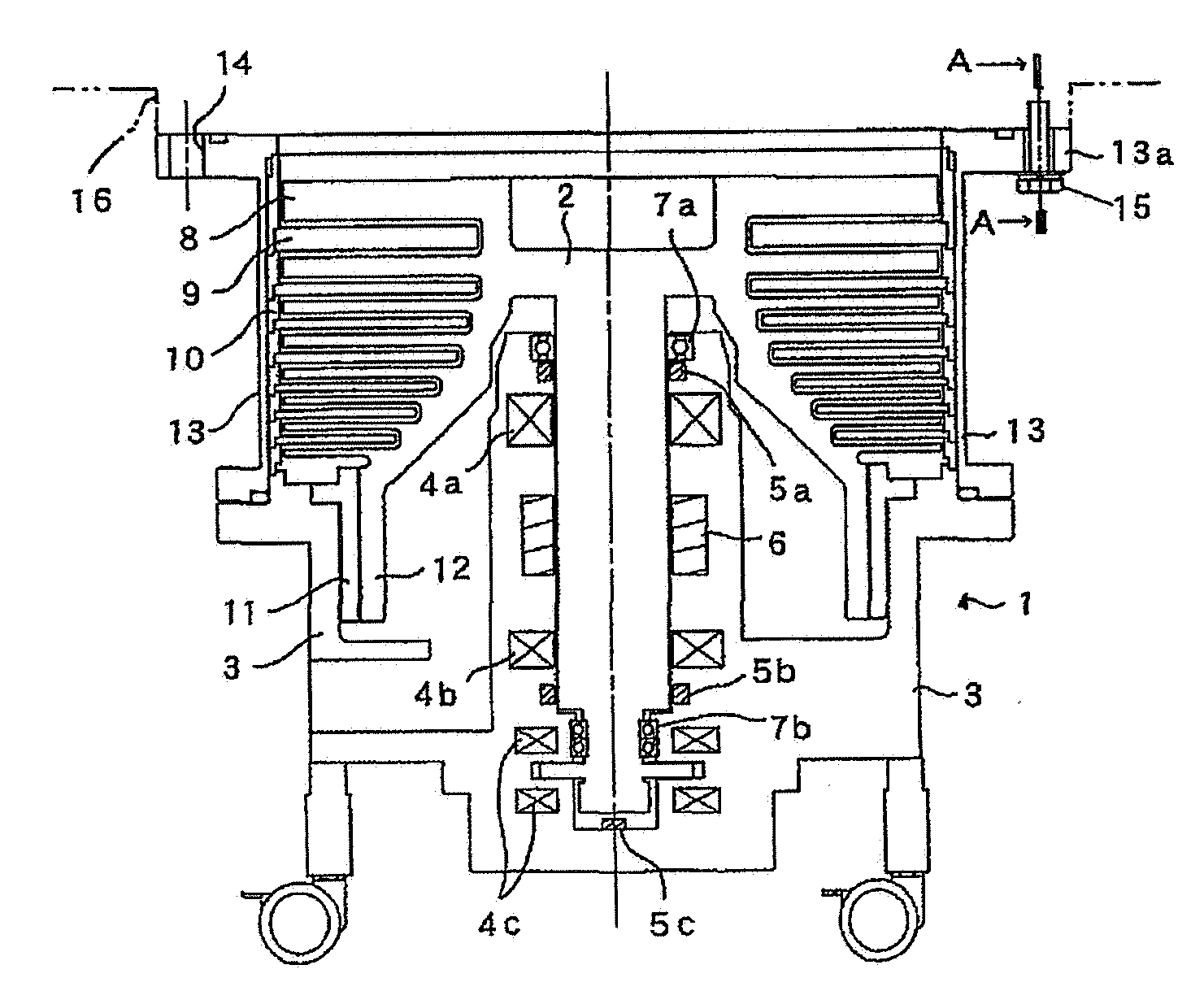
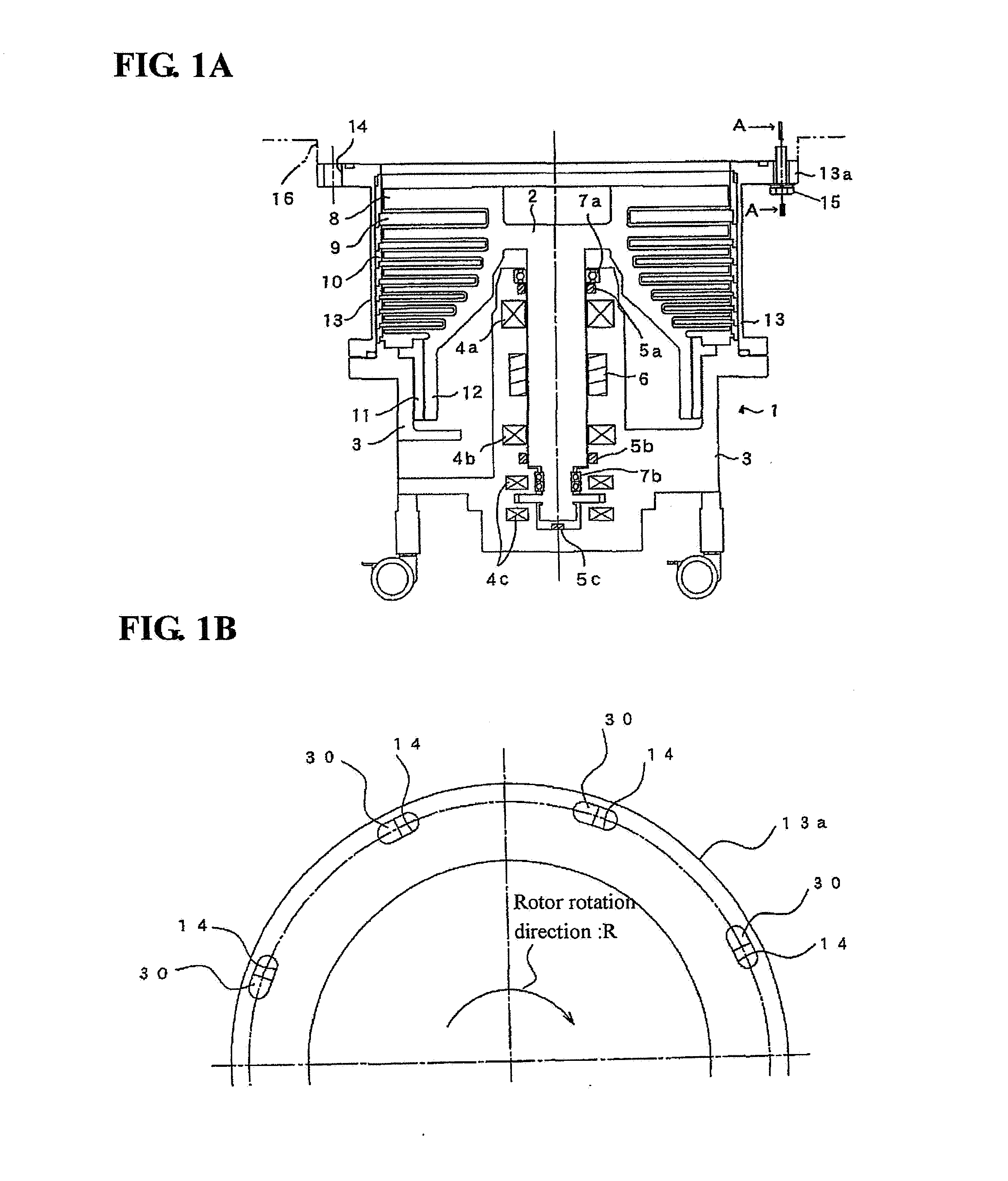
[0025]With reference to the drawings, an exemplary embodiment of the present invention will now be described. FIGS. 1A and 1B schematically show a turbo-molecular pump which employs a fastening structure relative to a target unit, according to one embodiment of the present invention, wherein FIG. 1A is a sectional view of the turbo-molecular pump, and FIG. 1B is a top plan view showing an upper half of a gas inlet flange of the turbo-molecular pump. The turbo-molecular pump 1 illustrated in FIGS. 1A and 1B is a magnetic bearing type which has a rotor 2 supported in a non-contact manner by three magnetic bearings 4a to 4c provided in a base 3. Each of the magnetic bearings 4a, 4b is a radial type, and the magnetic bearing 4c is an axial type.

[0026]The base 3 is provided with a motor 6 for rotationally driving the rotor 2, and three gap sensors 5a, 5b, 5c for detecting respective levitation positions of two touchdown bearings 7a, 7b and the rotor 2. A mechanical bearing is used for ea...


PUM


Abstract

Disclosed is a fastening structure for fastening a gas inlet flange of a turbo-molecular pump by a bolt to a flange of a target unit that will be subjected to a vacuum. The gas inlet flange has a slot-shaped bolt hole formed at a position adjacent to an outer peripheral edge thereof in such a manner that a longitudinal direction of the slot-shaped bolt hole approximately conforms to a direction tangential to the circumference of the gas inlet flange. A cushioning member made of foamed metal is disposed in the bolt hole. Even if an impact force occurs due to failure in the turbo-molecular pump, the cushioning member can receive the impact force to be applied from the gas inlet flange to the bolt.

Description

BACKGROUND OF THE INVENTION[0001]1. Field of the Invention[0002]The present invention relates to a fastening structure suitable for rotary vacuum pumps, such as a turbo-molecular pump or a molecular drag pump. The present invention also relates to a rotary vacuum pump using such a fastening structure.[0003]2. Description of the Related Art[0004]Heretofore, there has been known a turbo-molecular pump for use in discharging gas to produce a high vacuum. The turbo-molecular pump comprises a plurality of rotor blades arranged in a multistage manner, and a plurality of stator blades arranged in a multistage manner and in alternate relation to the respective rotor blades. The rotor blades and the stator blades make up a plurality of turbine blades, wherein the rotor blades are formed in a rotor adapted to be rotationally driven by a motor, and the stator blades are fixed to a base. There has also been known one type of turbo-molecular pump which includes a drag pump stage in addition to t...

Claims


Application Information

Patent Timeline
Patent Type & Authority Applications(United States)
IPC IPC(8): F04D29/60F16B43/00F16B35/00
CPCF04D19/042F04D27/0292F16B33/004F04D29/601
Inventor OISHI, KOUTA
Owner SHIMADZU CORP
Why Eureka
Try Eureka