Rapid 3D mapping using multielectrode position data

a multi-electrode position and 3d mapping technology, applied in the field of electrophysiology, can solve the problems of introducing components and complexity, affecting the accuracy of the results, and requiring separate 3d mapping/localization systems,

Inactive Publication Date: 2009-03-12
BOSTON SCI SCIMED INC
View PDF4 Cites 211 Cited by
  • Summary
  • Abstract
  • Description
  • Claims
  • Application Information

AI Technical Summary

Benefits of technology

[0008]In accordance with one aspect of the present invention, an electrophysiology (EP) system for use by an operator is provided. The system includes an interface having an output device comprising a display and an input device comprising a control panel, a processor, and code executing in the processor. The code comprises at least a first routine that is operative to respond to user-interaction through the control panel. Among other functionality, the code provides a selection of channels having associated EP data that is viewable on the display, informs a map module of any selections made among the selection of channels so as to link any EP data associated with any selections to the map module, permits positioning of the channels at respective locations on a template model to define a set-up, and saves the set-up for use in one or more procedures. The code is further operative to calculate values as a function of both the EP data and any positioning of the channels to said respective locations.

Problems solved by technology

The main disadvantage of these systems is the prohibitive cost involved with the equipment and the need for both a conventional EP recording system and a separate 3D mapping / localization system.
A number of catheter locating systems are known in the art, but each introduces components and complexity to EP procedures.
A difficulty remains, even if the location of the catheter is estimated based on fluorscopic guidance, in matching indwelling EP electrodes to sites on a cardiac model.
This problem is all the more difficult when the model is rendered in 3D.
Cardiac mapping, therefore, has required great effort at a time when the operator's attention needs to focus on the patient or in labs where cost is an impediment and a highly trained technician is not available to operate a complex 3D mapping system.

Method used


Image

  • Rapid 3D mapping using multielectrode position data
  • Rapid 3D mapping using multielectrode position data
  • Rapid 3D mapping using multielectrode position data

Examples


Embodiment Construction

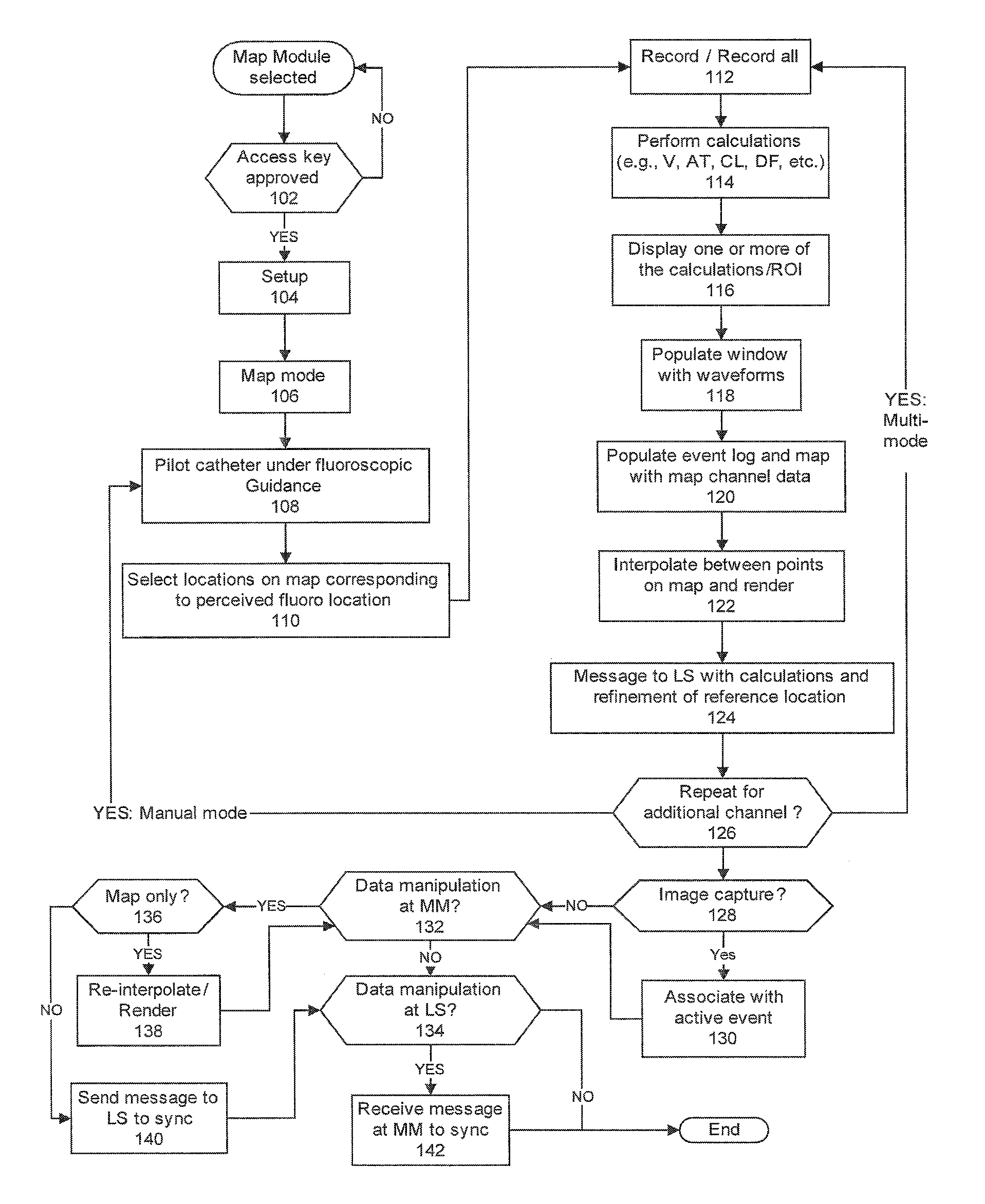
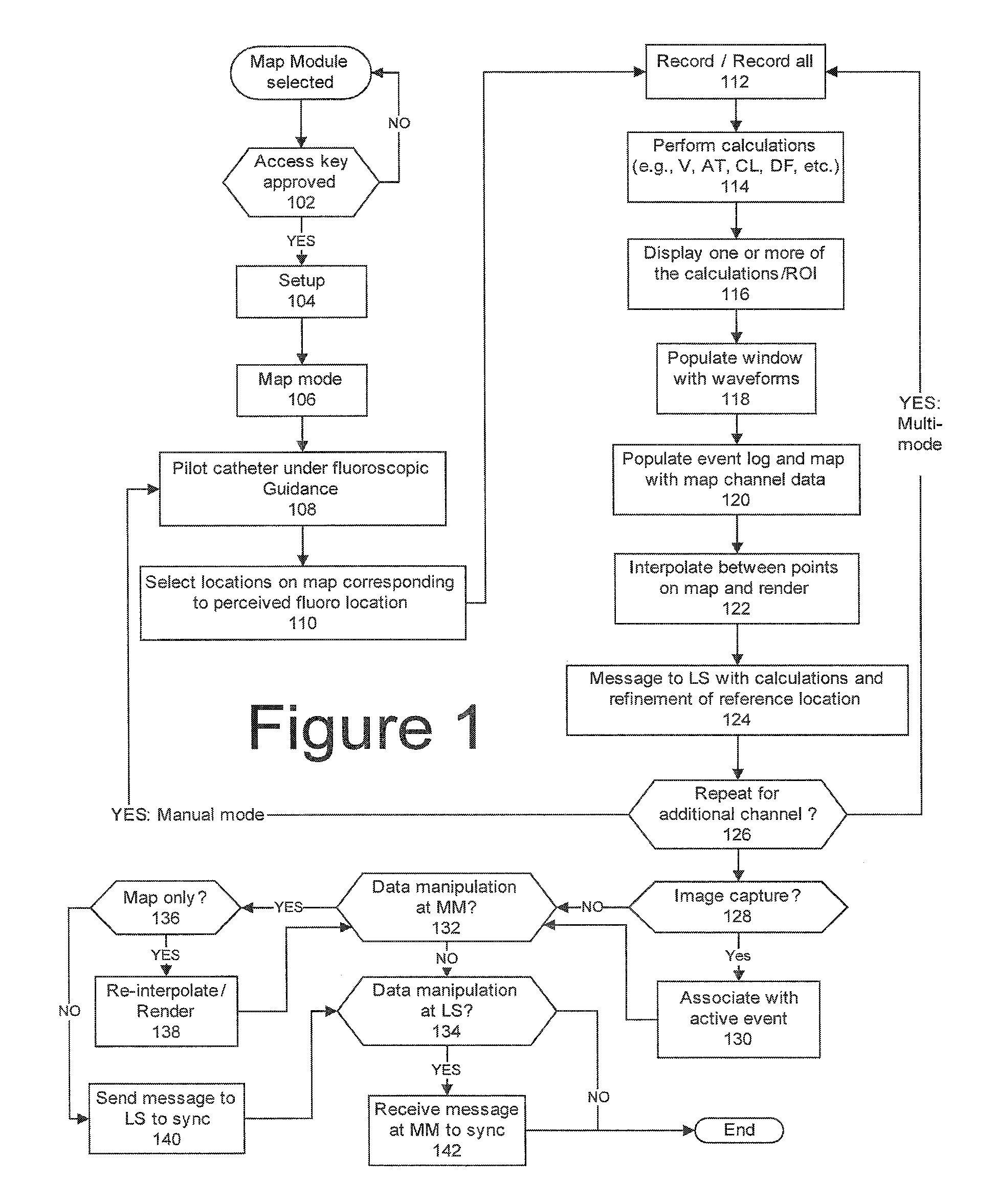
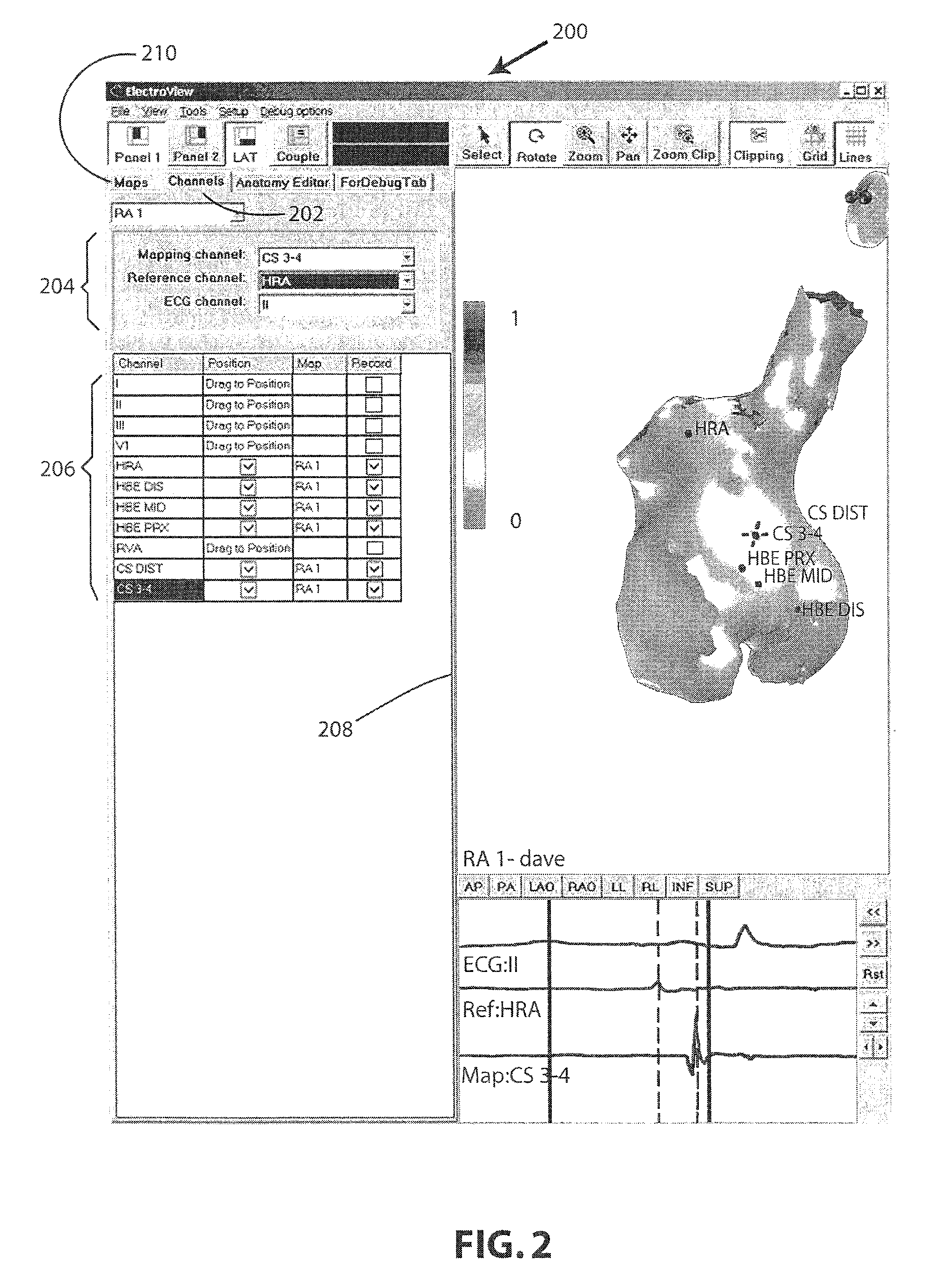
[0024]By way of overview and introduction, the present invention concerns 3-D mapping of cardiac data obtained during the course of an electrophysiology procedure. A segmented model of a heart can be acquired from a CT scan of a patient, or from a library of “typical” anatomies for patients having like characteristics. A software-based system populates the segmented model with data points that define a 3D map. The EP data at each data point is extracted from electrograms captured for one or more channels. The EP data for each channel is associated with an electrode, and the location of that electrode and hence the data point on the model can be defined on the map in several ways that simplify the equipment and operative steps that are required to construct a meaningful map, as described below.

[0025]In particular, and still by way of overview, the locations of one or more channels can be defined on a template model of a heart and stored for recall and use in a number of procedures. A...


PUM


Abstract

An electrophysiology (EP) system includes an interface for operator-interaction with the results of code executing therein. A template model can have channels positioned or repositioned thereupon by the user to define a set-up useful in rapid catheter positioning. Mapping operations can be performed without the requirement for precise catheter location determinations. A map module coordinates EP data associated with each selected channel and its associated position on the template model to provide this result, and can update the resulting map in the event that the channel or location is changed. Messaging and other dynamic features enable synchronized presentation of a myriad of EP data. Additional systems and methods are disclosed herein.

Description

[0001]This application claims the benefit of priority under 35 U.S.C. Section 119(e) of U.S. Provisional Application Ser. No. 60 / 916,749, filed May 8, 2007, which is hereby incorporated by reference in its entirety.FIELD OF THE INVENTION[0002]This invention is directed to improvements in electrophysiology (EP) systems and procedures including software that assists in data management across various systems in the EP laboratory including systems that provide electrogram capture, electrogram analysis, fluoroscopic display, and that permit, among other things, 3D colorized mapping of captured and analyzed data to provide an electrophysiologist with information in a form that assists in his or her diagnosis or documenting that an EP issue has been resolved.BACKGROUND OF THE INVENTION[0003]Many cardiac arrhythmias are caused by conduction defects that interfere with the propagation of normal electrical signals within the heart. The method adopted to treat arrhythmia is dependent on the na...

Claims


Application Information

Patent Timeline
Patent Type & Authority Applications(United States)
IPC IPC(8): A61B5/04
CPCA61B5/0422A61B5/044A61B6/503A61B6/5247G06T2207/30048G06T2200/04G06T2200/24G06T2207/10064G06T2207/20104G06T7/0012A61B5/287A61B5/339
Inventor MACADAM, DAVID P.MASHIMO, MINORUKUKLIK, PAWELSTOLLER, BRUCE
Owner BOSTON SCI SCIMED INC
Why Eureka
Try Eureka