Self-piercing element

a self-piercing element and piercing technology, applied in the direction of threaded fasteners, screwdrivers, manufacturing tools, etc., can solve the problems of torque-proof positioning, additional expenditure during shaping of the element, and non-rounded geometries that can be realized with these only to limited degrees, so as to improve the hold of the self-piercing element

Inactive Publication Date: 2009-03-19
BOLLHOFF VERBINDUNGSTECHNIK GMBH +1
View PDF34 Cites 29 Cited by
  • Summary
  • Abstract
  • Description
  • Claims
  • Application Information

AI Technical Summary

Benefits of technology

[0017]To further improve the hold of the self-piercing element in plastics, preferably in ductile deformable plastics, the functional head includes on its side facing the cutting geometry, a projecting contour beneath the head that supports a defined contact of the self-piercing element on the structural component. This can be optionally supplemented by a groove beneath the head, into which a material build-up can be received during seating of the self-piercing element, in order to support a seating of the functional head on the structural component.
[0018]The apparatus according to the invention for setting the self-piercing element in a structural component has the following features: a punching tool and a clinch tool, that are arranged opposing, and are movable parallel to their longitudinal axis in the joining direction, a die built from at least two segments arranged movably that defines an opening for the punching tool with the self-piercing element, while a position of the die segments can be adjusted such that a gap between the inside of the opening and the outside of the self-piercing element can be modified in its width depending on the material of the structural component and / or the conditions of the seating process, in order to optimally fasten the self-piercing element.

Problems solved by technology

However, non-rounded geometries can be realized with these only to limited degree.
However, this torque-proof positioning requires additional expenditure during shaping of the element, as well as during the process of attaching the element in the structural component.
At the same time, this additional expenditure is associated with an increased susceptibility to failure in the manufacturing process in comparison to simpler methods.
For cost reasons, the cutting geometry at the element as well as the corresponding die are usually supplied round, whereby particularly in full production run, the incompletely severed material connections between the hole waste pieces and the plastic part leads to an increased susceptibility to failure.
Due to the low ductile deformability of plastics, in particular, fiber reinforced plastics, an embossing of the plastic into the undercuts formed by punching nuts is not possible.

Method used


Image

  • Self-piercing element
  • Self-piercing element
  • Self-piercing element

Examples


Embodiment Construction

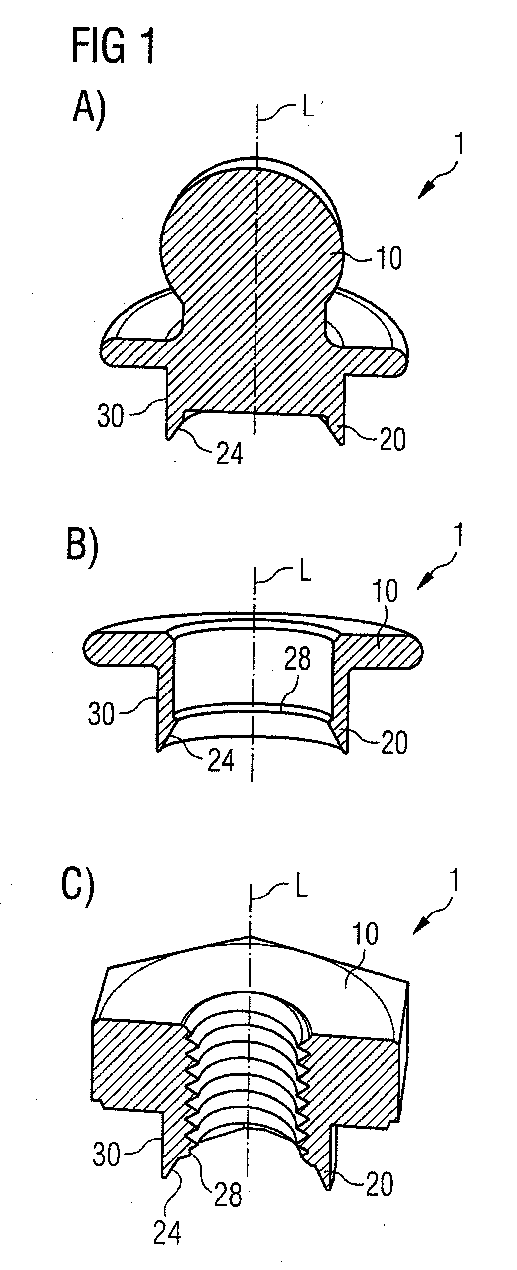
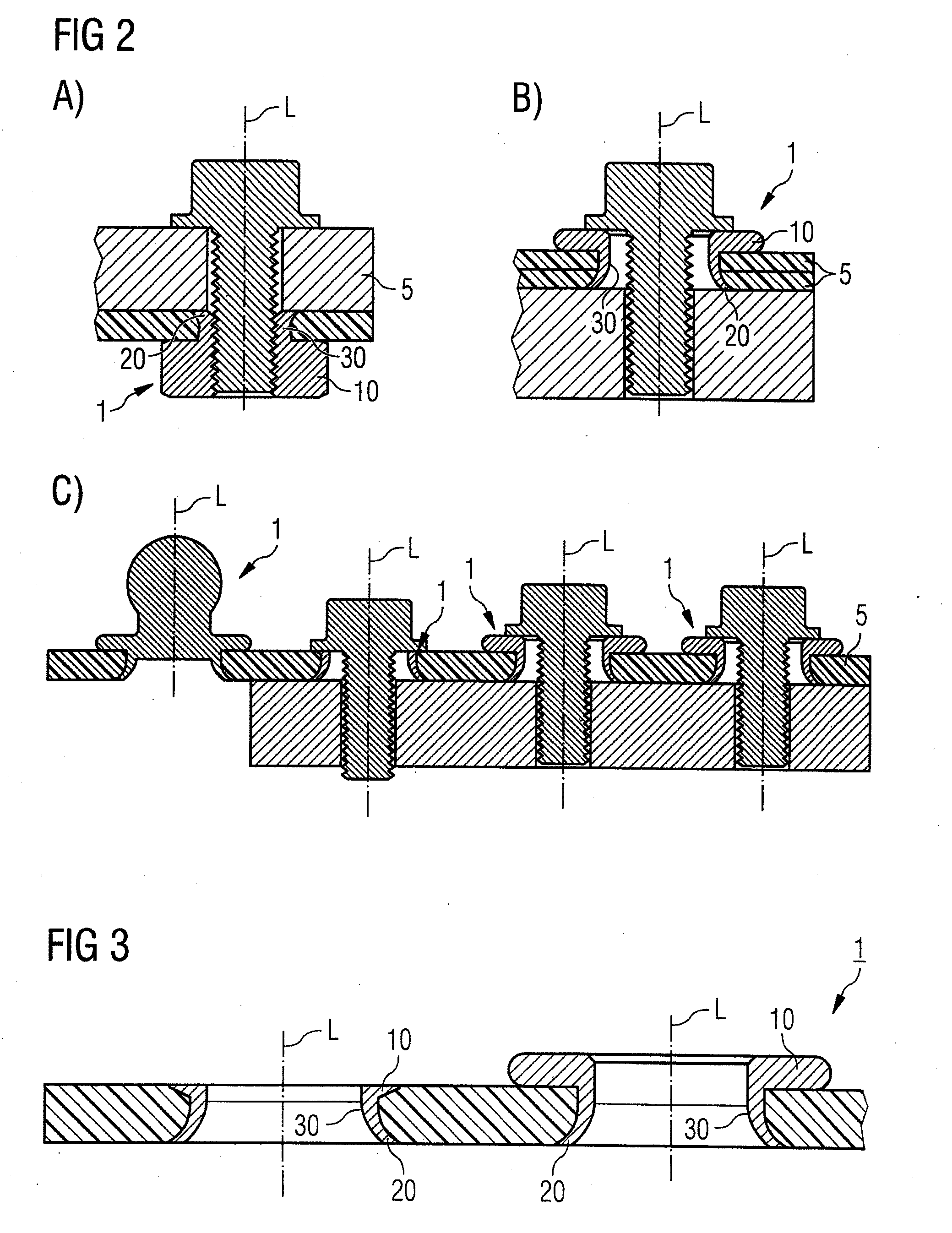
[0042]The FIGS. 1A-C show different embodiments of the self-piercing element 1. Relative to its longitudinal axis L, the self-piercing element 1 includes a functional head 10 at one end coaxial to its longitudinal axis L. This functional head 10 is formed differently depending on the function to be realized at the structural component 5. According to one alternative, the functional head 10 is composed of a spherical head according to FIG. 1A. This serves, for example, the attachment of a snap connection. According to a further alternative, the functional head 10 forms a supporting flange, as shown in FIG. 1C. The self-piercing element from FIG. 1C serves as a hole reinforcement in order to fasten the structural component 5 to a frame structure, for example, by means of screws. According to the construction shown in FIG. 1B, the functional head 10 is supported on the structural component 5. FIG. 1C shows a further alternative, in which the functional head 10 includes a threaded eleme...


PUM

PropertyMeasurementUnit
cone angleaaaaaaaaaa
lengthaaaaaaaaaa
angleaaaaaaaaaa

Abstract

The present invention discloses a self-piercing element, that can be fastened to a structural component by means of piercing and beading. Additionally, the present invention discloses an apparatus for seating the self-piercing element and a corresponding method. The self-piercing element comprises a functional head, a seat geometry and a cutting geometry, while the cutting geometry has a radially outwards arranged, centering exterior bevel, a radially inward arranged interior bevel and a cutting edge arranged in between.

Description

FIELD OF THE INVENTION[0001]The present invention relates to a self-piercing element, which can be connected by means of piercing and beading to a structural component, preferably to a structural component composed of plastic in motor vehicle manufacturing. In addition, the present invention relates to a structural component, in which such a self-piercing element is fastened, an apparatus for inserting such a self-piercing element, and a method for fastening, with which such a self-piercing element can be fastened in the structural component.BACKGROUND OF THE INVENTION[0002]In manufacturing motor vehicles, large-area structural components are attached, for example, as a splash guard in the underbody area and in the front end area of the vehicle. These structural components, which are also used in other areas of the motor vehicle, are composed of different plastics, with or without fiber reinforcement. The materials, for example, are SCT, GMT, CFRP, PP long fiber or similar. These st...

Claims


Application Information

Patent Timeline
Patent Type & Authority Applications(United States)
IPC IPC(8): B23P11/00F16B13/06
CPCB21J15/025B21J15/36B23P19/062Y10T29/53774F16B37/062Y10T29/49833F16B19/086B29C65/562B29C65/568B29C65/64B29C65/7437B29C66/1122B29C66/21B29C66/41B29C66/474B29C66/721B29C66/7212B29C66/742B29C66/8161B29C66/83221B29C2793/0045F16C11/0604F16C11/0695B29K2307/04B29K2309/08
Inventor STUMPF, MICHAELMARXKORS, ANDREASBACHMEIER, STEPHANPEKAL, CHRISTOPHSIMON, JORGLANGER, MATTHIAS
Owner BOLLHOFF VERBINDUNGSTECHNIK GMBH
Why Eureka
Try Eureka