Fuel Vent Valve And Improvement Thereof

Inactive Publication Date: 2009-03-19
RAVAL - AGRI COOP SOCIETIES
View PDF23 Cites 17 Cited by
  • Summary
  • Abstract
  • Description
  • Claims
  • Application Information

AI Technical Summary

Benefits of technology

[0022]Pspring denotes the effective pressure applied by the biasing eff

Problems solved by technology

The valve is an integration of a valve and double check valve serving as a pressure holder (‘pre

Method used


Image

  • Fuel Vent Valve And Improvement Thereof
  • Fuel Vent Valve And Improvement Thereof
  • Fuel Vent Valve And Improvement Thereof

Examples


Embodiment Construction

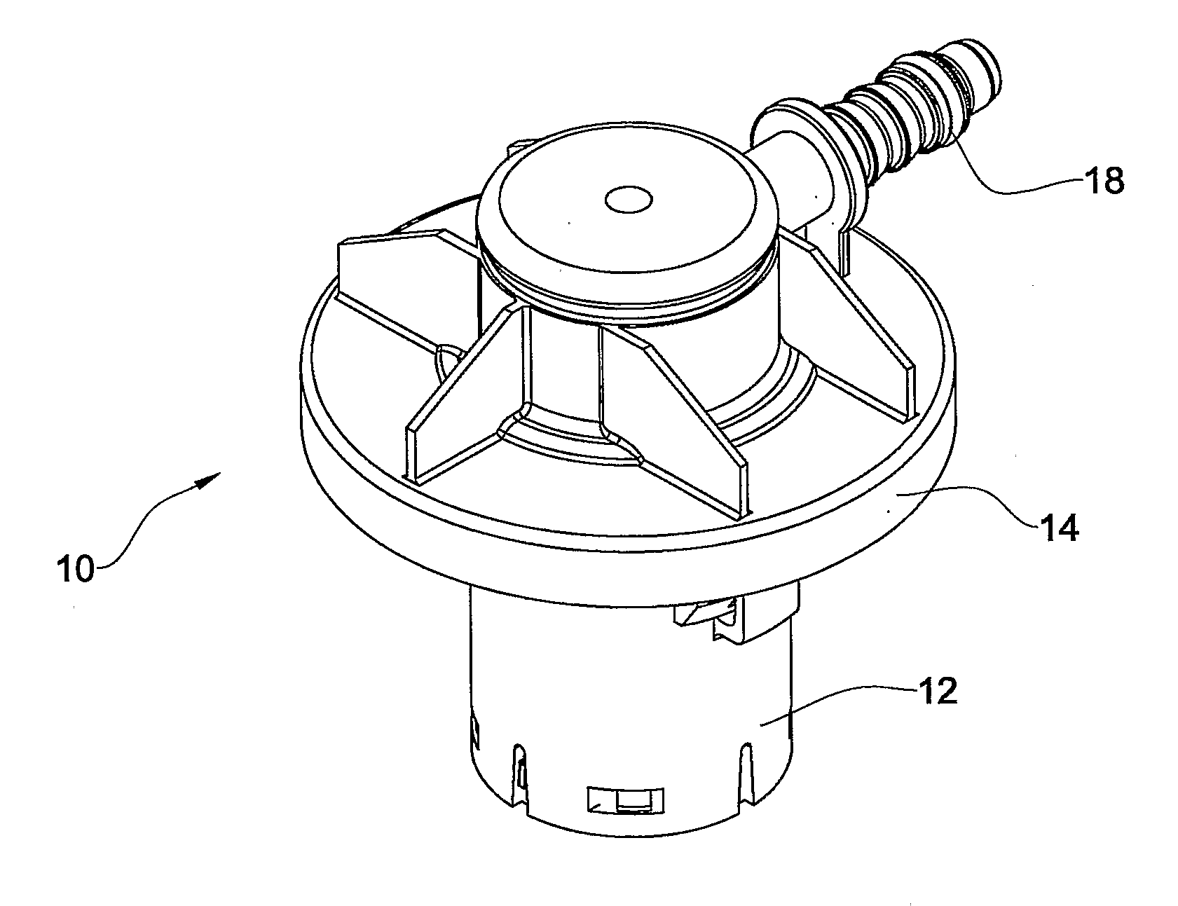
[0035]In FIG. 1 there is illustrated a valve in accordance with the present invention generally designated 10 comprising a cylindrical housing 12 depending from a flange 14 fitted for sealing attachments over a top surface of a fuel tank (not shown) such that the housing 12 extends into the space of the fuel tank. Extending from an upper portion of the flange 14 there is a fluid outlet port 18 connectable to a vapor recovery system such as a carbon canister, etc. (not shown).

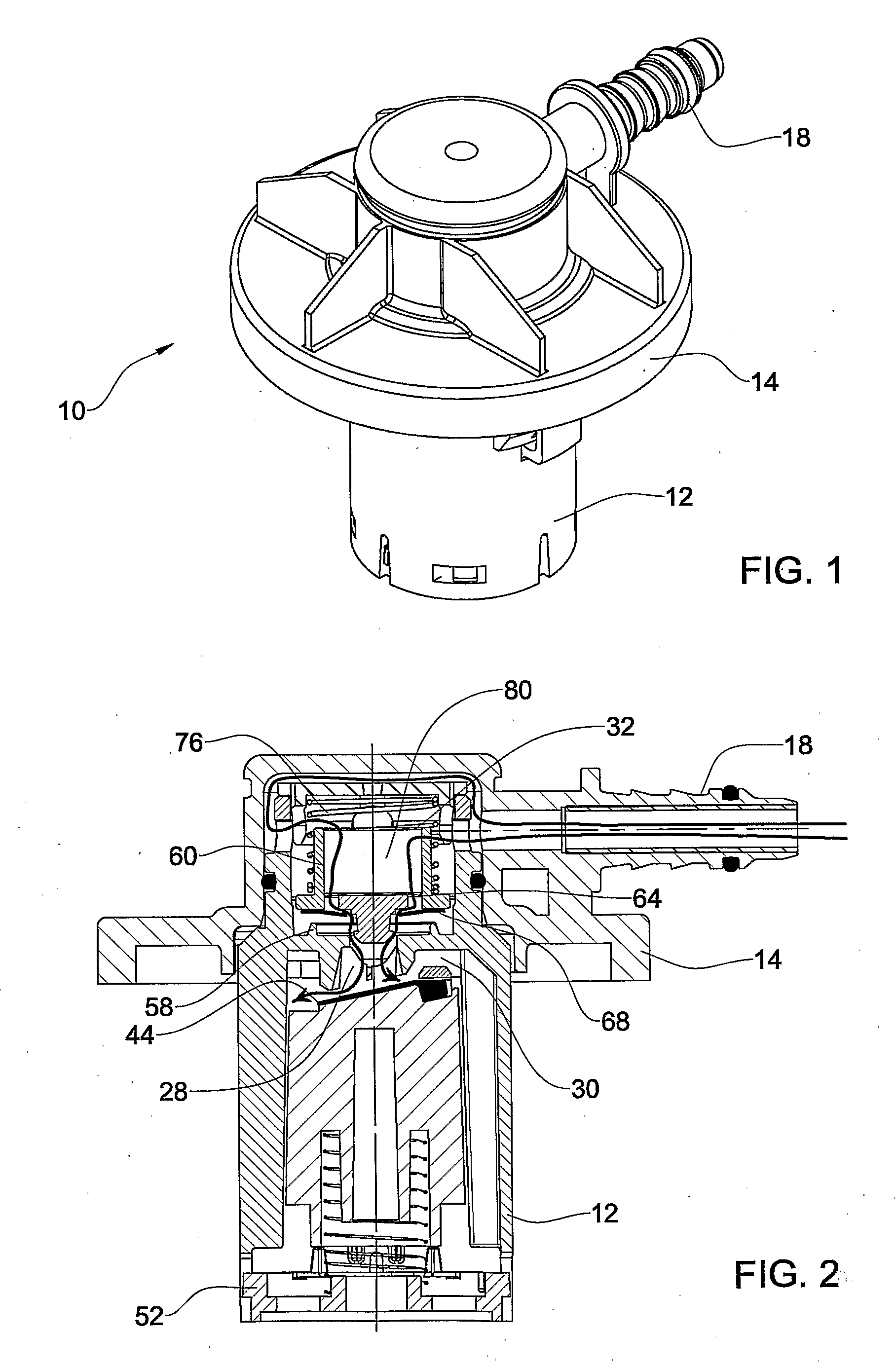
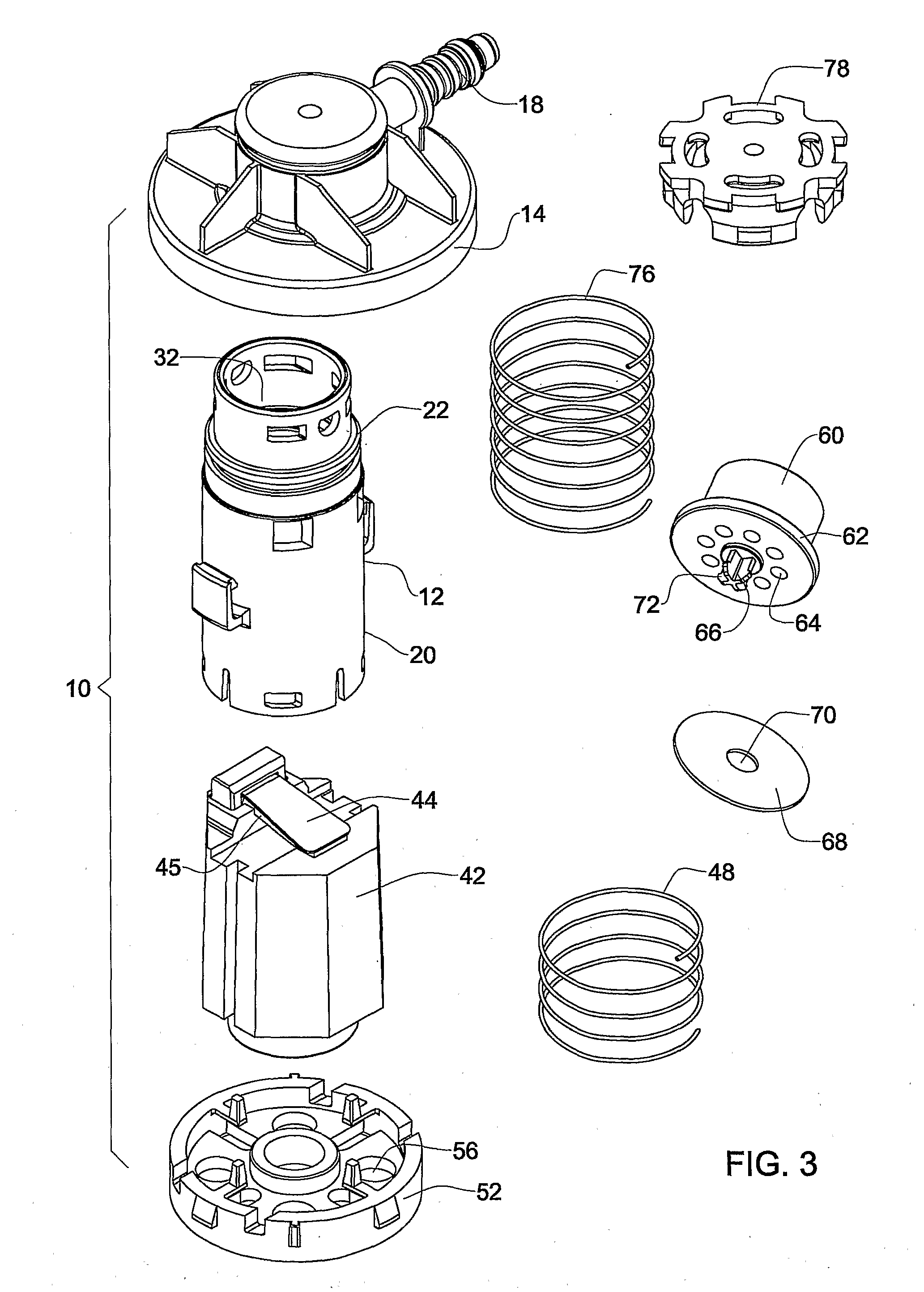
[0036]It can further be seen in the section views of FIGS. 2, 4 to 6 and in the exterior view of FIG. 3, the cylindrical housing 12 comprising a bottom portion 20 and an upper portion 22 partitioned from one another by a partition wall 26 (best seen in FIG. 5) formed with a flow path 28 extending between a bottom space 30 and top space 32 as will be discussed hereinafter. The housing 20 is snap fitted into the flange 14 and is sealingly retained by a sealing O-ring 34. The flow path passage 28 is formed at its b...


PUM


Abstract

A fuel valve comprising a primary valve and a pressure responsive auxiliary valve, both being axially accommodated and displaceable within a common housing formed with a fluid inlet and a fluid outlet port, and a partition extending between the primary valve and the auxiliary valve. The partition comprising a flow passage extending between a primary port at a bottom face of the partition and an auxiliary port at a top face of the partition. The primary port is sealable by a sealing member of the primary valve and the auxiliary port sealable by a sealing member of the auxiliary valve.

Description

FIELD OF THE INVENTION[0001]The present invention generally relates to improvements in rollover vent valves and more particularly the invention is concerned with a rollover vent valve with a two way valve serving as a pressure / under pressure relief valve and as a check valve.BACKGROUND OF THE INVENTION[0002]In a fuel system of vehicle there is typically provided a fuel tank associated with a fuel pump module connected by a fuel delivery line to the fuel rail and injectors of the engine, with a plurality of valve means provided to regulate fuel and vapor flow.[0003]One of such valves is the rollover vent valve is designed to allow, on the one hand, for the venting of fuel vapor from a vehicle fuel tank to the atmosphere or to a vapor recovery system such as a carbon canister, and, on the other hand, to ensure the closure of the valve under certain conditions. These conditions can arise either when, as a result of excessive filling of the tank fuel, passes into the valve or, and most ...

Claims


Application Information

Patent Timeline
IPC IPC(8): F16K31/22
CPCF16K24/042Y10T137/053B60K15/03F16K31/22
Inventor VULKAN, OMEREHRMAN, MOSHEBAR-LEV, AVIGAIL
Owner RAVAL - AGRI COOP SOCIETIES
Why Eureka
Try Eureka