Torch spacing apparatus

Active Publication Date: 2009-03-19
EIGEN SYST
View PDF3 Cites 20 Cited by
  • Summary
  • Abstract
  • Description
  • Claims
  • Application Information

AI Technical Summary

Problems solved by technology

There are problems with this type of torch arrangement whereby to ensure the spacing between torches (or torch heads) is mi...

Method used


Image

  • Torch spacing apparatus
  • Torch spacing apparatus
  • Torch spacing apparatus

Examples


Embodiment Construction

[0021]The following description will describe the invention in relation to preferred embodiments of the invention, namely a tool substitution mechanism. The invention is in no way limited to these preferred embodiments as they are purely to exemplify the invention only and that possible variations and modifications would be readily apparent without departing from the scope of the invention.

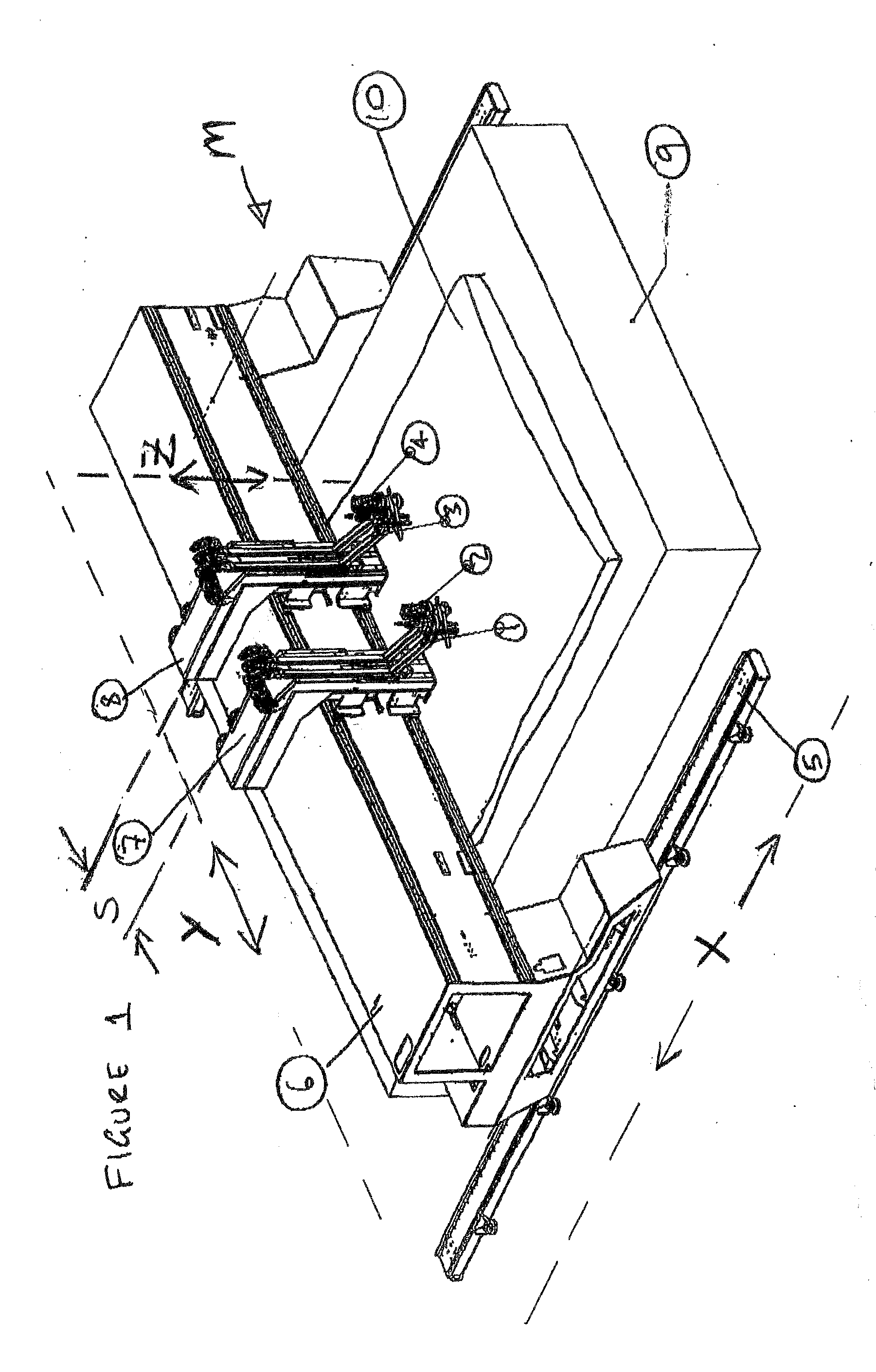
[0022]FIG. 1 is a schematic showing a typical current method for a plasma or flame cutting machine M for cutting a product such as steel for example, whereby cutting tools 1, 2, 3, 4 such as plasma or flame torches are mounted on a movable gantry 6 straddling a cutting table 9. The gantry 6 has moveable carriages 7&8 thereon. Cutting tools 1-4 are lined up side by side in front of carriages 7&8 thereby limiting the spacing between same type tooling. Gantry 6 travels in an X axis (see item “X” and the double ended arrow defining the direction of the axis and travel as used throughout the drawing fi...


PUM


Abstract

A torch spacing apparatus for a plasma or flame cutting machine includes a gantry that is guided to travel in an X axis. Mounted to the gantry is at least one carriage that is/are guided to travel in a Y axis. Mounted to each carriage are selected tooling having at least two cutting torches mounted thereon with an active cutting tool in an active cutting position. The carriage is mounted to enable tooling substitution whereby the torch spacing apparatus includes a substitution mechanism which is operatively attached to the carriage and tooling such that the said substitution mechanism is adapted to allow the position of a cutting torch or active cutting torch to be substituted with another cutting torch currently in the active position to space the torches accordingly by rotating the cutting tools about a Z axis.

Description

[0001]The invention relates to a torch spacing apparatus adapted to enable various cutting torches to maintain close spacing and to a method of substituting tooling. The invention is directed particularly but not solely towards a pivot system apparatus for substituting cutting torches for precision high definition cutting machines for steel or any other suitable material.BACKGROUND OF INVENTION [0002]Normally on flame and plasma cutting machines having a bridge, the bridge is fitted with multiple tooling such as oxy fuel torches and multiple plasma cutting torches on movable carriages. The cutting machine is fitted with multiple carriages where each carriage is fitted with one each of the different cutting heads of either plasma or oxy fuel or other cutting heads such as marking, laser cutting, drilling or the like. The cutting machine allows for the spacing of the carriages to be adjusted by manual or automatic methods. The carriage spacing is then set and all the carriages support...

Claims


Application Information

Patent Timeline
IPC IPC(8): B23K9/00
CPCB23K7/06B23K37/0211B23K26/0853B23K7/10
Inventor FORLONG, MURRAY HOULTON
Owner EIGEN SYST
Why Eureka
Try Eureka