Electrical resistance measuring device for tires, and method thereof

a technology of electric resistance and measuring device, which is applied in the direction of vehicle tyre testing, instruments, roads, etc., can solve the problems of poor working efficiency in measurement, inability to measure the electrical resistance value in a similar manner, and inability to maintain accuracy of measurement, so as to achieve the effect of ensuring the electrical conductivity characteristics of tires, reducing the difficulty of measurement, and improving the accuracy of measuremen

Inactive Publication Date: 2009-03-19
BRIDGESTONE CORP
View PDF6 Cites 10 Cited by
  • Summary
  • Abstract
  • Description
  • Claims
  • Application Information

AI Technical Summary

Benefits of technology

[0021]An electrical resistance value between a tread part and a bead part can be measured automatically, and moreover, the accuracy of measurement can be maintained. The electrical conductivity characteristics of a tire can be assured and the measurement work can be simplified significantly.

Problems solved by technology

This improves the rolling resistance of the tire, but on the other hand increases an electrical resistance value of tread rubber, thus causing a problem that static electricity generated on a vehicle is hardly discharged to a road surface.
In order to increase the accuracy of measurement of the electrical resistance value, the number of times of measurement needs to be increased, and therefore the working efficiency in the measurement is poor.
However, in this tire with the high electrically conductive rubber ribbon laminated thereon, it is impossible to measure the electrical resistance value in a manner similar to that of the conventional tire manufacturing method of applying the tread rubber layer onto the molding drum.
This is because in the conventional tire manufacturing method a place to be measured is one sheet of tread rubber layer while in the recent tire manufacturing method an elongated high electrically conductive ribbon is the target to be measured, and therefore with the conventional measuring method, the number of measured places becomes huge, thus decreasing the working efficiency and also making it difficult to increase the accuracy of measurement.
However, this measurement work takes a long time.

Method used


Image

  • Electrical resistance measuring device for tires, and method thereof
  • Electrical resistance measuring device for tires, and method thereof
  • Electrical resistance measuring device for tires, and method thereof

Examples


Embodiment Construction

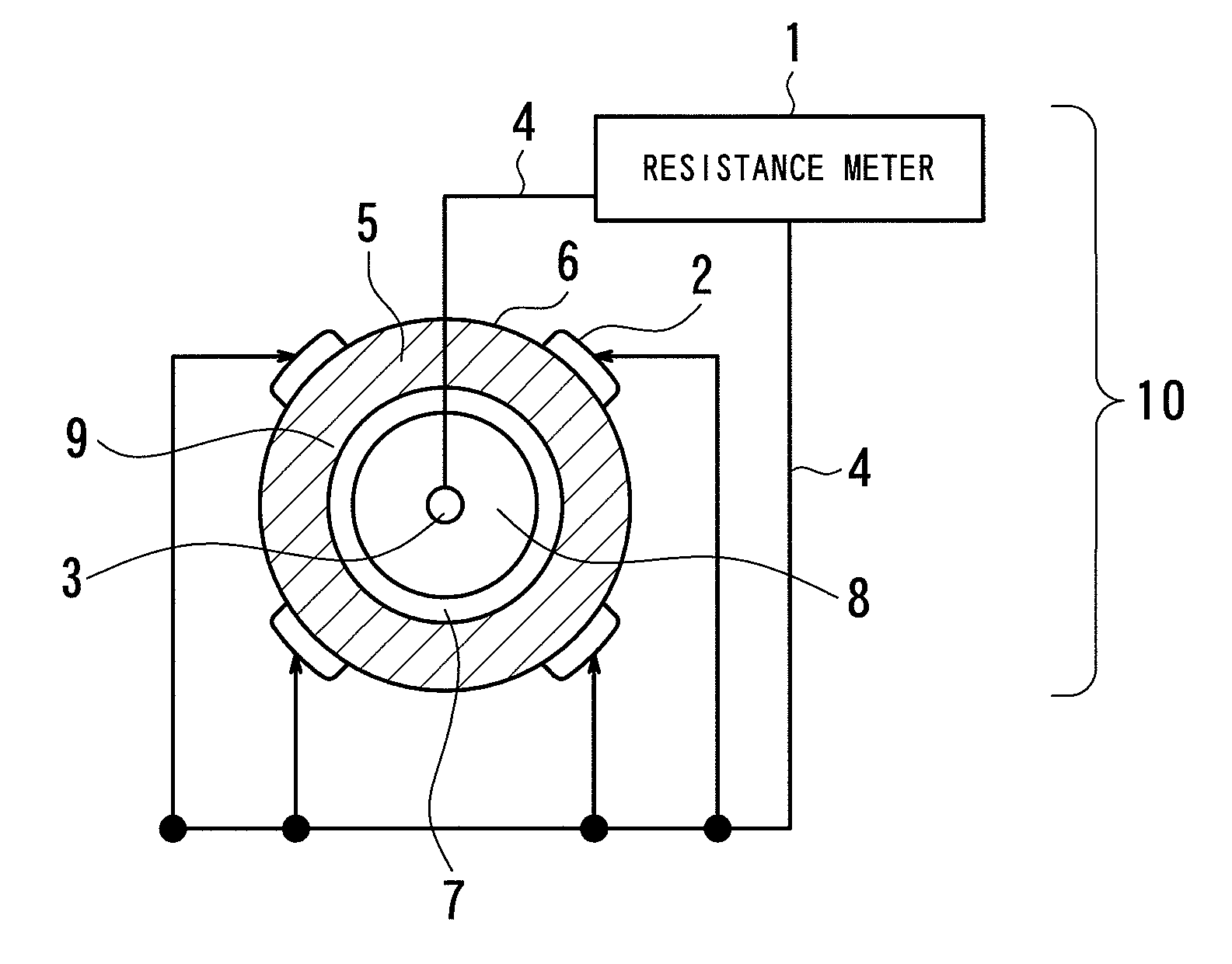
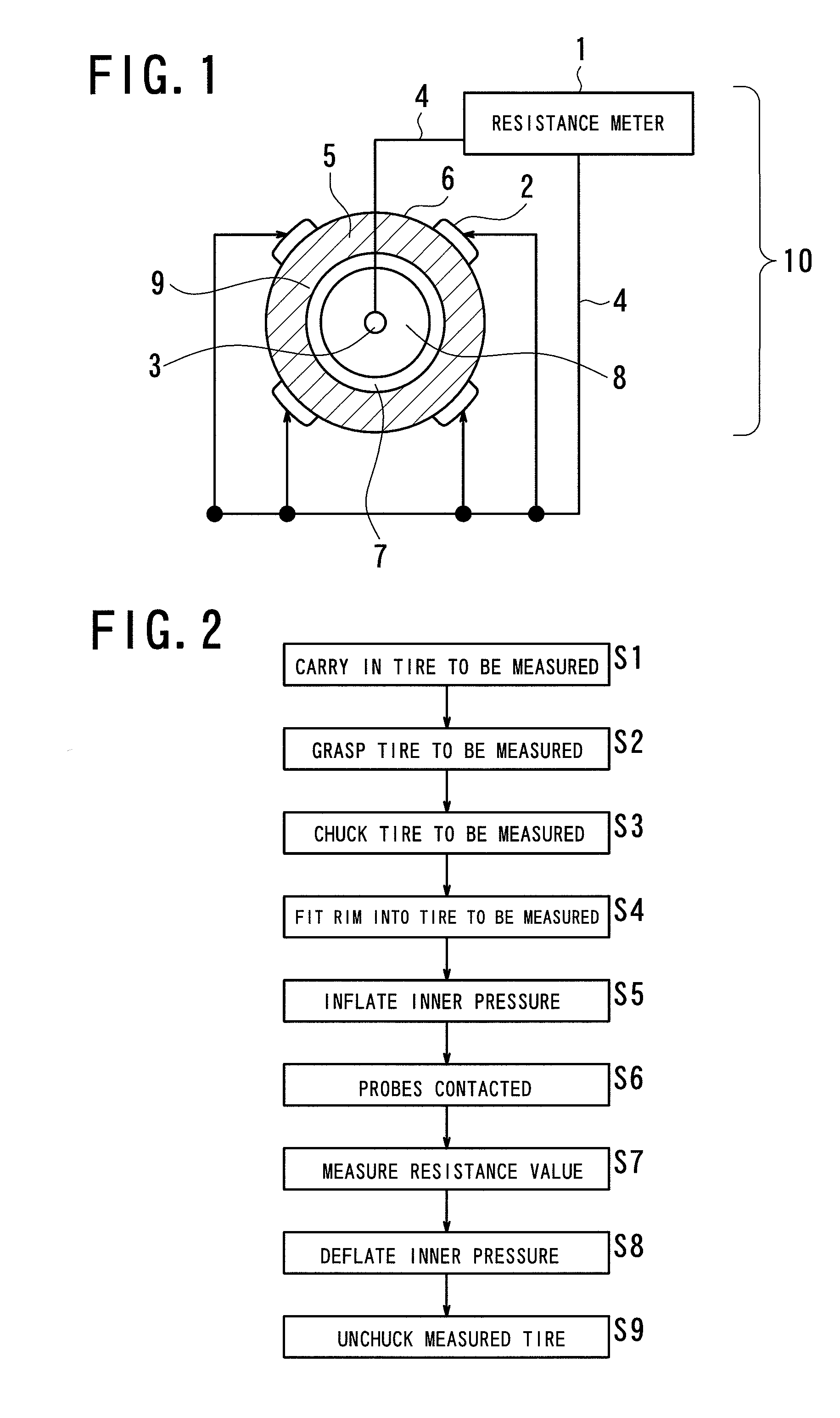
[0036]With reference to FIG. 1, a conceptual diagram showing the entire configuration of a first embodiment is described. Reference numeral 10 of FIG. 1 represents an electrical resistance measuring device for tires that includes a resistance meter 1, four first probes 2 arranged around a tread part 6 of a tire 5, a second probe 3, and an electric cord 4. The electric cord 4 is connected to the first and second probes 2 and 3, and other end thereof is connected to the resistance meter 1. As the quality of the material of the first and second probes 2 and 3, it is desirable to use a material with a low resistivity and a low degree of hardness. In addition, reference numeral 5 represents the tire, 6; the tread part, 7; the rim part, 8; the disc wheel, and 9; the bead part.

[0037]The contact surface of the first probe 2 is set to have substantially the same shape as that of the outer peripheral surface of the tread part 6 of the tire. For a tire having a high electrically conductive rub...


PUM


Abstract

To provide a resistance measuring device not requiring a long time for the resistance measurement work of a tire and maintaining the accuracy of measurement to assure the electrical conductivity characteristics of the tire and a method thereof.
An electrical resistance measuring device for tires 10 comprises first and second probes 2, 3 for measuring an electrical resistance value of a tire 5, wherein the first probes 2 abut on a plurality of portions in an outer peripheral surface of a tread part 6 and the second probe 3 abuts on a periphery of a center part of a tire 5, and thereby an electrical resistance value between the tread part 6 and the bead part 9 is measured.

Description

TECHNICAL FIELD[0001]The present invention relates to electrical resistance measuring devices for tires that measure the electrical resistance of a tire compounding conductive rubber in tread rubber, and a method thereof.BACKGROUND ART[0002]Conventionally, a low electrically conductive material, such as silica, is compounded in rubber of a tire in order to improve rolling resistance of the tire. This improves the rolling resistance of the tire, but on the other hand increases an electrical resistance value of tread rubber, thus causing a problem that static electricity generated on a vehicle is hardly discharged to a road surface. Then, a method has been employed, in which one sheet of tread rubber layer made by compounding conductive rubber in the tread rubber is applied to a forming drum, thereby manufacturing a tire, and in this method the electrical resistance value of the tread rubber layer is measured before forming. In order to increase the accuracy of measurement of the elec...

Claims


Application Information

Patent Timeline
Patent Type & Authority Applications(United States)
IPC IPC(8): G01R27/08G01M17/02
CPCB60C19/08G01N2033/0085G01N27/041
Inventor MURAKAMI, KOSEIUCHIDA, NORIMICHIGOTO, TAKAHIRO
Owner BRIDGESTONE CORP
Why Eureka
Try Eureka