
Antenna and electrical apparatus including the same

a technology of electrical equipment and antenna, applied in the direction of elongated active element feed, resonant antenna, radiating element structure, etc., can solve the problems of inability to meet a tolerance, normal operation, and restrictions on the degree of freedom in the installation method of mobile terminals or electrical equipment, etc., to achieve the effect of convenient installation

Inactive Publication Date: 2009-03-19
HITACHI CABLE
View PDF13 Cites 32 Cited by
  • Summary
  • Abstract
  • Description
  • Claims
  • Application Information

AI Technical Summary

Benefits of technology

[0032]According to the antenna of the invention, when the antenna is built in the chassis of the mobile terminal or the electrical apparatus, it has the loop structure in the position located at a distance from away the metallic (conductor) parts close thereto due to a limit to the built-in space, which results in that the electrical noises invading the antenna can be made less because it is possible to keep the loop structure causing the invitation of the electrical noises far way from each of the transmission path and generation source of the electrical noises.
[0033]According to the antenna of the invention, when the antenna is built in the chassis of the mobile terminal or the electrical apparatus, it includes the ground to face the metallic (conductor) part(s) so as to be close to the metallic (conductor) part(s), and another antenna element between the antenna element and the ground. As a result, it is possible to keep the main element relating to the transmission / reception of the electric wave far away from the ground so as to maintain the radiation characteristics of the antenna. Moreover, the matching characteristics can also be enhanced with still another element disposed between each of these elements, and the ground.
[0034]When the antenna is built in the chassis of the mobile terminal or the electrical apparatus, the feeder cable used in the antenna of the invention is disposed in a direction of shortening the connection distance between the antenna and the transmission / reception tuner (module). As a result, it is possible to suppress an increase in transmission loss, and deterioration of the strengths of the transmission signal and the received signal. Moreover, it is possible to shorten the path length in which the feeder cable itself is influenced by the electrical noises.
[0038](2) It is possible to realize the built-in antenna which is readily installed with the space saving.

Problems solved by technology

In the case of the antenna as described above, during the movement or reinstallation of the mobile terminal or the electrical apparatus, a user is usually associated with the botherations such as a method of distributing a cable or the like, a failure of the antenna due to repetition of attachment and detachment of a connector or an unanticipated trouble, and a restriction on the degree of freedom in a method of installing the mobile terminal or the electrical apparatus.
However, when an S / N ratio which is defined by a ratio of a strength of a received signal received at the antenna, to a strength of an electrical noises existing in the circumference of the mobile terminal or the electrical apparatus, or in the chassis thereof is poor, especially in the reception operation of the system for transmitting / receiving the digital electric wave, it is impossible to meet a tolerance, in a normal operation, for a received signal processing executed in a tuner for transmission / reception (module).
As a result, the received signal can not be regenerated in the form of an image and a sound in some cases.
However, with the antenna structure and the method of building the antenna in the chassis described in the known examples described above, the measures are not sufficiently taken to cope with the electrical noises.
As has been described above, although with the conventional technique, the antenna is readily built in the chassis of the mobile terminal or the electrical apparatus, the measures are not sufficiently taken to cope with the electrical noises existing in the chassis which is necessary, especially, during the reception of the transmission and reception of the digital signal electric wave.
However, the possibility that these measures thus taken causes rise in fabricating cost of the mobile terminal or electrical apparatus itself is high.

Method used


Image

  • Antenna and electrical apparatus including the same
  • Antenna and electrical apparatus including the same
  • Antenna and electrical apparatus including the same

Examples


embodiment 1

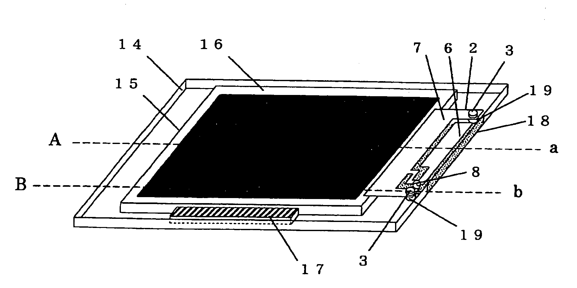
[0148 of an antenna according to the present invention which solves the problem about the influence of the electrical noises and which is realized in accordance with the consideration and design method described above will be described in detail below with reference to FIGS. 13A to 13C to FIGS. 20A to 20B.

[0149]FIGS. 13A to 13C respectively show examples of plate antennas 201, 202 and 203 which are designed and embodied in accordance with the consideration about the antenna design described above. Each of the plate antennas 201, 202 and 203 is composed of antenna elements 6 and 60, and a ground 7 which are formed in conductor plate-like shapes, respectively. Feeding points 8 are set at positions shown in FIGS. 13A to 13C, respectively. Also, the actual feeding is carried out by using a coaxial cable (not shown) or the like. Thus, each of the plate antennas 201, 202 and 203 has fixing screws through holes 10 for antenna fixing. Each of the plate antennas 201, 202 and 203 was fabricat...


PUM


Abstract

An antenna includes antenna elements, an electric power feeding portion for supplying an electric power to each of the antenna elements, a short-circuit element for antenna matching electrically connected to the electric power feeding portion, and a ground connected to the short-circuit element. The antenna is built in a chassis made of a metal, and the chassis made of a metal and the ground are electrically connected to each other.

Description

[0001]The present application is based on Japanese patent application No. 2007-199711 filed on Jul. 31, 2007, the entire contents of which are incorporated herein by reference.BACKGROUND OF THE INVENTION[0002]1. Field of the Invention[0003]The present invention relates to an antenna which is built in a chassis of a mobile terminal or an appliance and through / at which an electric wave of a digital broadcasting is transmitted / received, and an electrical apparatus including the antenna, and more particularly to a structure of an antenna for realizing measures taken to cope with an influence of electrical noises existing in a chassis in which the antenna is built, and a method of building the antenna in a chassis.[0004]2. Description of the Related Art[0005]In recent years, a digital broadcasting system starts to come into wide use by being substituted for an analog broadcasting system including terrestrial television broadcastings. Moreover, the switching from the analog broadcastings ...

Claims


Application Information

Patent Timeline
Patent Type & Authority Applications(United States)
IPC IPC(8): H01Q1/38H01Q1/24
CPCH01Q9/42H01Q1/2266
Inventor IKEGAYA, MORIHIKO
Owner HITACHI CABLE
Learn More