Electro-optical device, electronic apparatus and method of detecting indicating object

a technology of optical devices and electronic devices, applied in the direction of instruments, electric digital data processing, computing, etc., can solve the problems of image quality deterioration, burn-in, and deterioration of touch determination precision, and achieve the effect of high precision

Inactive Publication Date: 2009-03-19
SEIKO EPSON CORP
View PDF1 Cites 21 Cited by
  • Summary
  • Abstract
  • Description
  • Claims
  • Application Information

AI Technical Summary

Benefits of technology

[0011]An advantage of some aspects of the invention is that it provides an electro-optical device capable of determining whether or not an indicating object is appro...

Problems solved by technology

In an electro-optical device using liquid crystal, that is, in a liquid crystal device, if a DC voltage is applied to the liquid crystal, image quality deterioration such as burn-in is caused.
However, in the case where the polarity of the liquid crystal is inverted in frame cycles, since the common potential Vcom is changed for each frame, an error occurs between the gradation of a reference image and the gradation of an image which is the object of comparison (hereinafter, referred to as a target image) due to the level change of the common potential Vcom and thus the precision of the touch determination deteriorates.
The error in the gradation due to the inversi...

Method used


Image

  • Electro-optical device, electronic apparatus and method of detecting indicating object
  • Electro-optical device, electronic apparatus and method of detecting indicating object
  • Electro-optical device, electronic apparatus and method of detecting indicating object

Examples


first embodiment

1. Basic Configuration

[0041]An electro-optical device according to a first embodiment of the invention uses liquid crystal as an electro-optical material. The electro-optical device 1 includes a liquid crystal panel AA (which is an example of an electro-optical panel) as a main portion. The liquid crystal panel AA is formed by attaching a device substrate, on which thin-film transistors (hereinafter, referred to as TFTs) are formed as switching elements, and a counter substrate to each other with a predetermined gap such that the electrode forming surfaces thereof face each other and filling the liquid crystal in the gap.

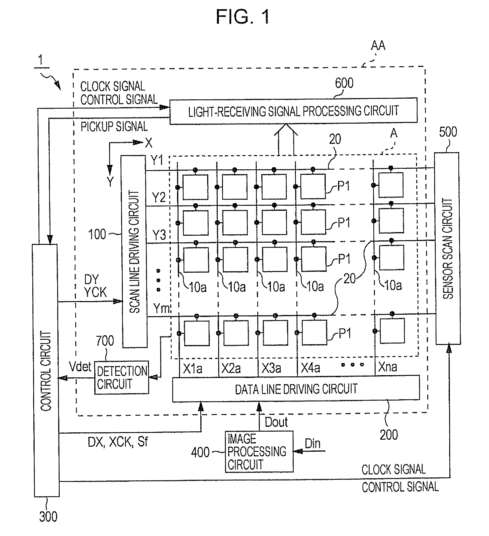
[0042]1First, the basic configuration of the electro-optical device according to the present embodiment will be described with reference to FIG. 1. FIG. 1 is a block diagram showing the overall configuration of the electro-optical device 1 according to the first embodiment.

[0043]As shown in FIG. 1, the electro-optical device 1 includes the liquid crystal panel AA, a...

second embodiment

4. Second Embodiment

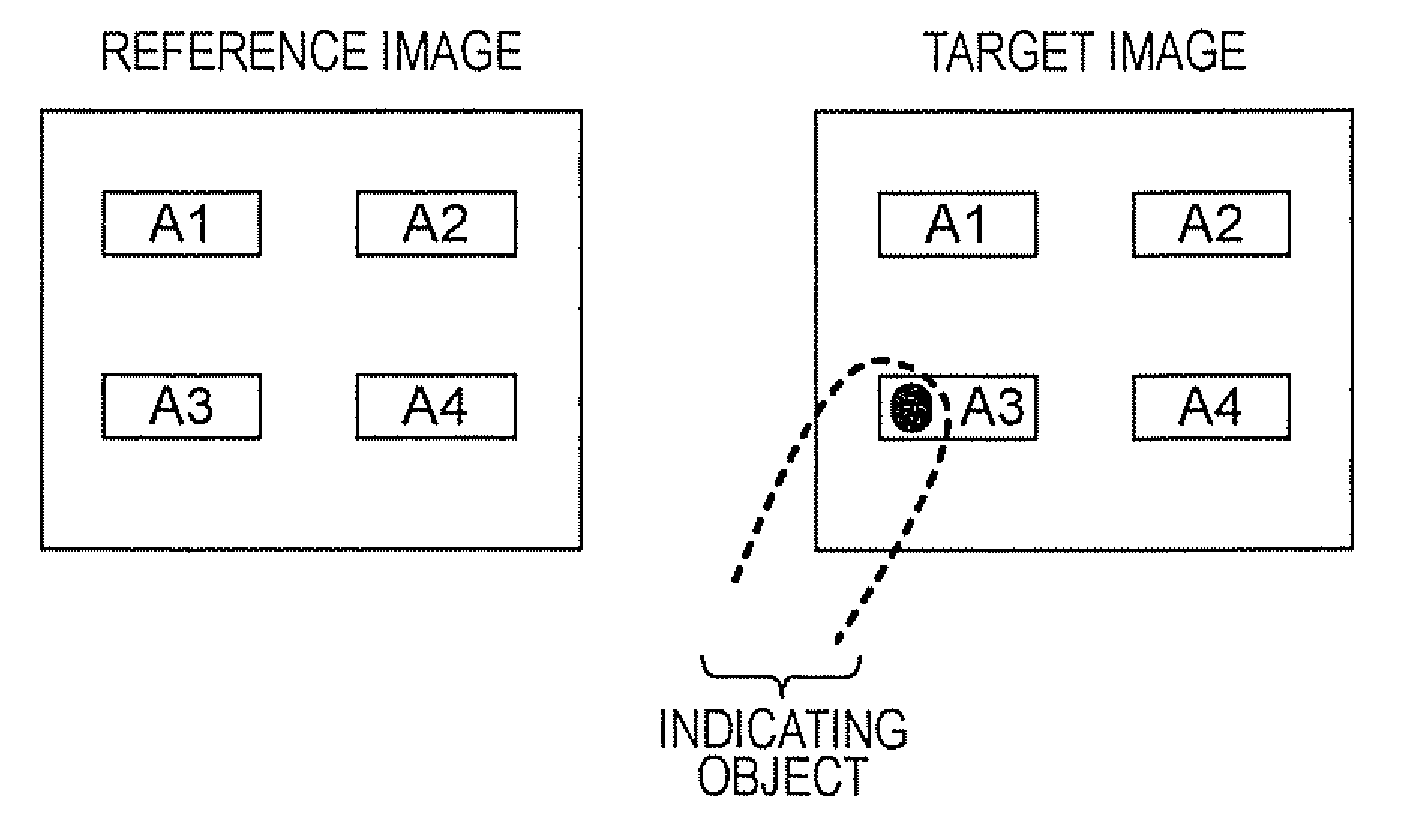
[0087]Next, an electro-optical device according to a second embodiment will be described with reference to FIG. 9. The configuration of the electro-optical device according to the second embodiment is equal to that of the electro-optical device according to the first embodiment described with reference to FIGS. 1 to 8. FIG. 9 is a flowchart illustrating an initialization process at the time of touch determination according to the second embodiment of the invention (FIG. 9A) and a flowchart illustrating a touch determination process based on the comparison between a reference image and a target image (FIG. 9B), according to the second embodiment.

[0088]First, as shown in FIG. 9A, as the initialization process, under the control of the control circuit 300, for example, in the odd-numbered frame at a frame rate of 60 frames per second, at a timing when the ground potential GND is supplied to the second electrode 1b which is the common electrode, the Vcom level which ...


PUM


Abstract

Provided is a device for driving first and second electrodes and an electro-optical element including a material having optical characteristics that vary with an applied voltage. The device includes: a driving unit which drives the electro-optical element between first and second driving states; a display unit which displays an image based on the optical characteristics of the electro-optical element; a pickup unit that outputs image data according to the amount of incident light; a first memory which fetches/stores the image data as reference image data; a second memory which fetches/stores the image data as target image data; a difference image data generating unit which generates difference image data from a difference between the reference and target image data; and a control unit which controls the write/read of the first and second memories such that the driving states corresponding to the reference image data and the target image data become equal.

Description

BACKGROUND[0001]1. Technical Field[0002]The present invention relates to an electro-optical device including a light detecting function for specifying the position of an indicating object such as a finger and detecting an area by detecting external light, and an electronic apparatus including the electro-optical device.[0003]2. Related Art[0004]In an electro-optical device using liquid crystal, that is, in a liquid crystal device, if a DC voltage is applied to the liquid crystal, image quality deterioration such as burn-in is caused. Accordingly, an AC voltage is applied to the liquid crystal.[0005]In the liquid crystal device, a plurality of pixel circuits are arranged in a matrix. In each of the pixel circuits, if a scan signal becomes a high level, a transistor is turned on and thus a data potential supplied via a data line is applied to the liquid crystal and is held in a storage capacitor. A liquid crystal element is configured by interposing the liquid crystal between a pixel ...

Claims


Application Information

Patent Timeline
IPC IPC(8): G06F3/042G09G3/36
CPCG06F3/042G06F3/0412G09G3/36G09G3/20G01J1/42G02F1/133
Inventor CHINO, TAKETO
Owner SEIKO EPSON CORP
Why Eureka
Try Eureka