Eureka AIR delivers breakthrough ideas for toughest innovation challenges, trusted by R&D personnel around the world.

Auxiliary rotary bearing system

Active Publication Date: 2009-03-19
HAMILTON SUNDSTRAND CORP
View PDF0 Cites 14 Cited by
  • Summary
  • Abstract
  • Description
  • Claims
  • Application Information

AI Technical Summary

Benefits of technology

[0003]For machinery comprising rotary components attached to at least one drive shaft, at least one rotary bearing to position the drive shaft with a rotational freedom of movement about a drive shaft axis and associated stationary components with at least one predetermined clearance from the rotary components, the invention generally comprises apparatus for preventing the rotary components from contacting the stationary components upon failure of the bearing, comprising: a rotary backup bearing sleeve attached to the drive shaft proximate the bearing comprising a rotary radial surface relative to the drive shaft axis and a rotary axial surface relative to the drive shaft axis; and a stationary backup bearing collar mounted proximate the rotary backup bearing sleeve comprising a

Problems solved by technology

Although relatively service-free, bearings for such rotating machinery have a limited service life.
Particularly in the case of such rotating machinery subject to unfavourable environments, such as those with ambient contamination or temperature extremes, and such machinery that employs sealed bearings, the service life of these bearings may at times be less than predicted.
In such instances, the bearings may be subject to catastrophic failure whilst in service.
Such failure may cause damage to the machinery and adversely affect ambient conditions, such as due to sparks, smoke, heat and odour.

Method used


Image

  • Auxiliary rotary bearing system
  • Auxiliary rotary bearing system
  • Auxiliary rotary bearing system

Examples


Embodiment Construction

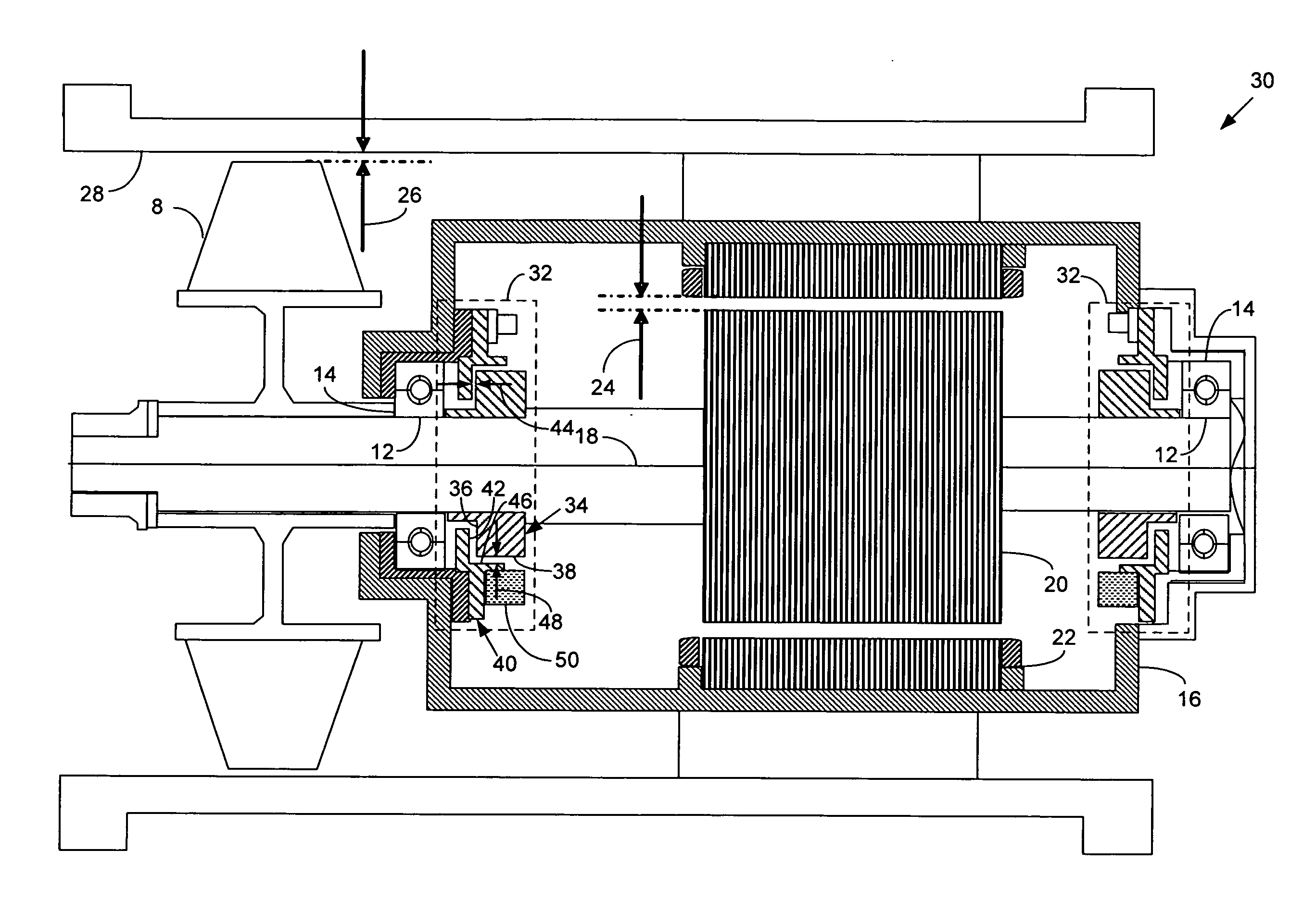
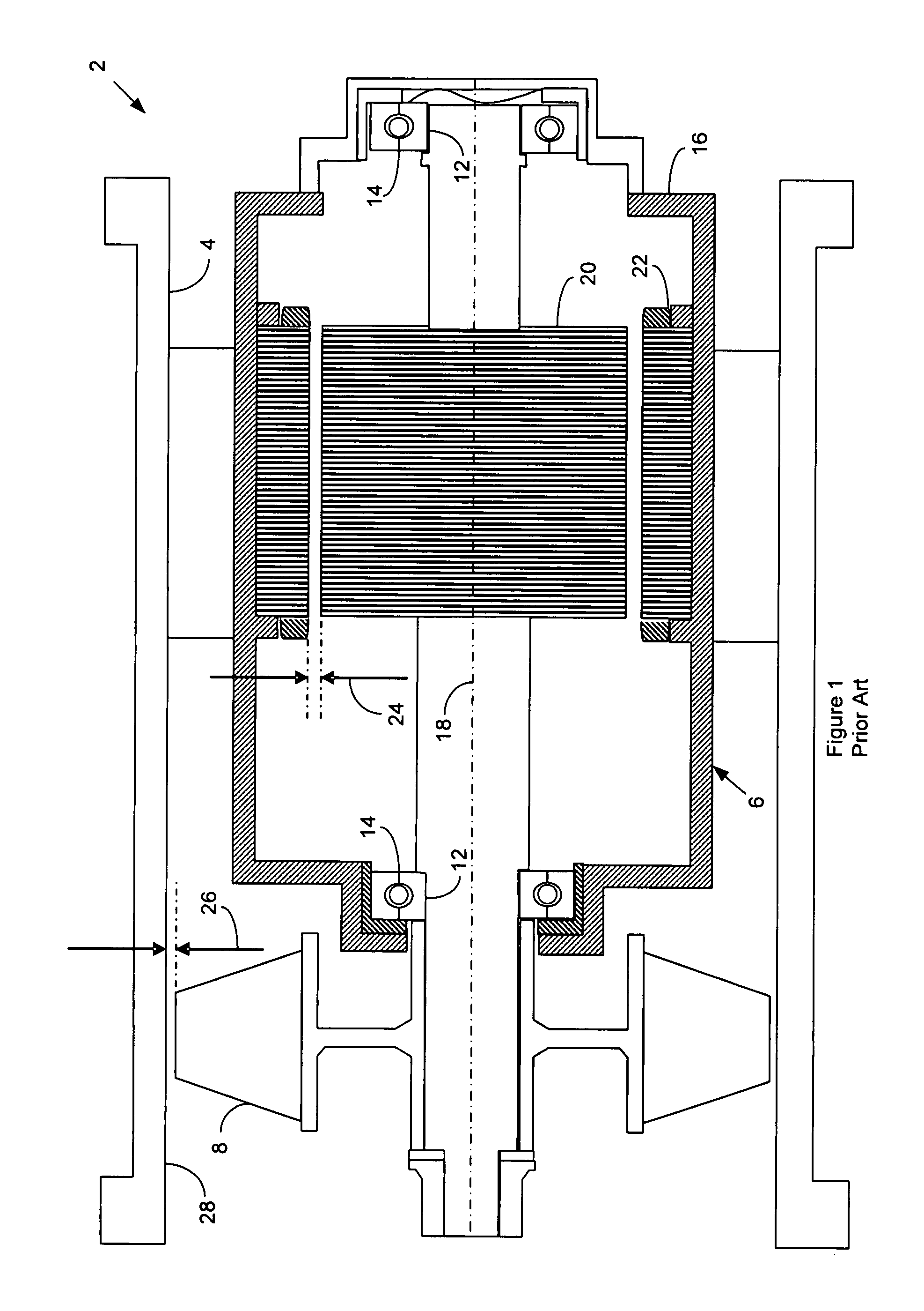
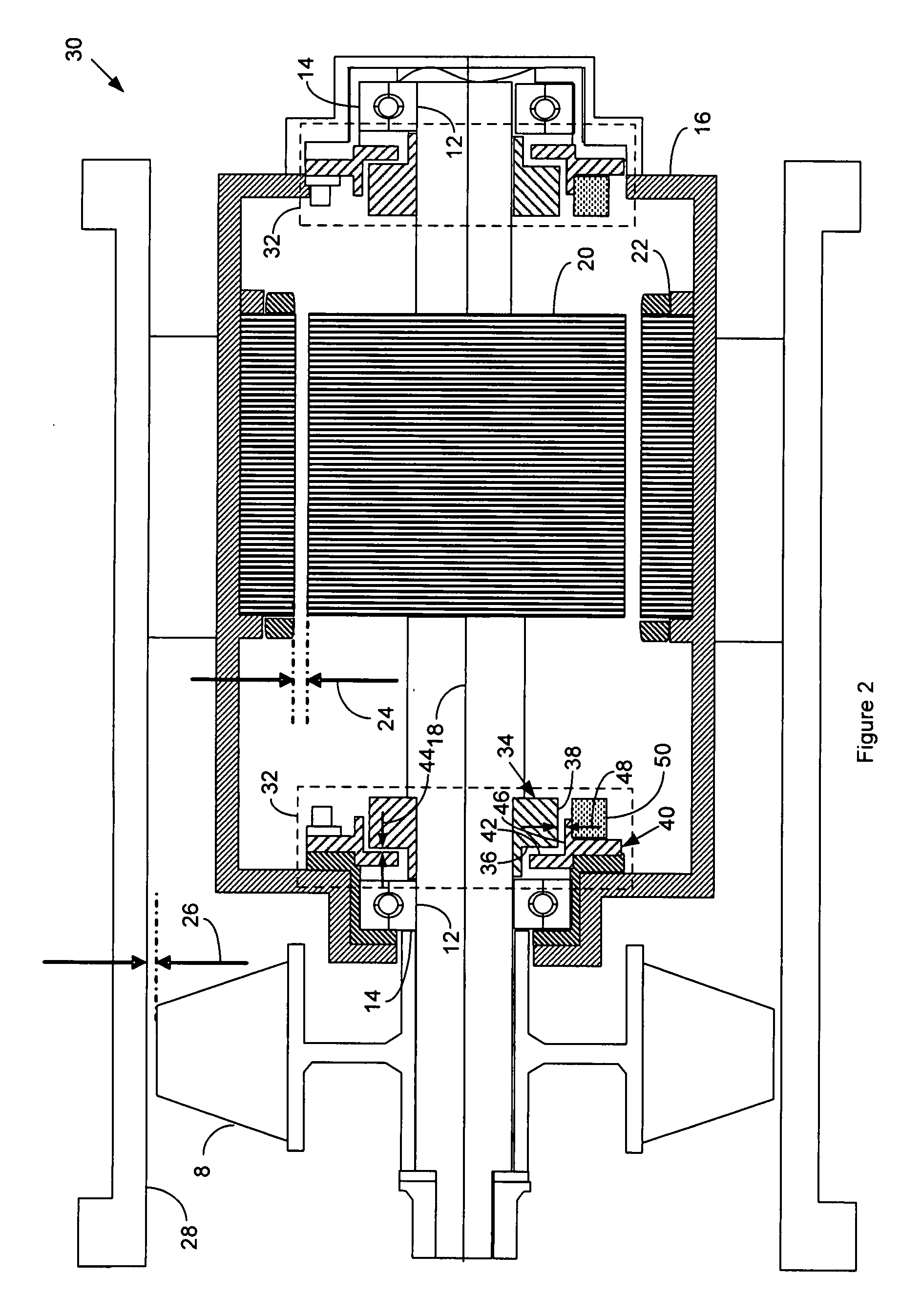
[0006]FIG. 1 is a cut-away side view of an apparatus comprising rotary machinery according to the prior art. By way of example only, the apparatus in FIG. 1 comprises an electrically powered axial fan. The fan 2 has an outer housing 4 that supports and encloses rotary machinery that comprises an electrical motor 6 coupled to an axial fan blade 8 by means of a drive shaft 10. The drive shaft 10 has two rotary support surfaces that comprise shaft journals 12. Each shaft journal 12 has an associated rotary bearing comprising a shaft bearing 14 that mounts to a motor housing 16 for the motor 6. The bearings 14 position and align the drive shaft 10 within the motor 6 with a rotational freedom of movement along shaft axis of rotation 18. The electrical motor 6 also comprises a rotor 20 and a stator 22. The drive shaft 10 mounts the rotor 20 and the motor housing 16 mounts the stator 22 to at least partially circumscribe the rotor 20 with a predetermined stator clearance 24. The fan blade ...


PUM


Abstract

For machinery comprising rotary components attached to at least one drive shaft, at least one rotary bearing to position the drive shaft with a rotational freedom of movement about a drive shaft axis and associated stationary components with at least one predetermined clearance from the rotary components, apparatus to prevent the rotary components from contacting the stationary components upon failure of the bearing, comprises: a rotary backup bearing sleeve attached to the drive shaft proximate the bearing comprising a rotary radial surface relative to the drive shaft axis and a rotary axial surface relative to the drive shaft axis; and a stationary backup bearing collar mounted proximate the rotary backup bearing sleeve comprising a stationary radial surface relative to the drive shaft axis proximate the rotary radial surface with a predetermined axial clearance and a stationary axial surface relative to the drive shaft axis proximate the rotary radial surface with a predetermined axial clearance; wherein the rotary backup bearing sleeve contacts the stationary backup bearing collar upon failure of the bearing and the predetermined axial and radial clearances limit deviation of the rotary components to less than the predetermined clearance from the stationary components.

Description

FIELD OF THE INVENTION[0001]The invention relates to a bearing system for rotary machinery, and more particularly to a rotary bearing system that has fail-safe functionality.BACKGROUND OF THE INVENTION[0002]Rotating equipment is used in many relatively service-free applications, such as electric motors for fans, blowers and pumps. Although relatively service-free, bearings for such rotating machinery have a limited service life. Particularly in the case of such rotating machinery subject to unfavourable environments, such as those with ambient contamination or temperature extremes, and such machinery that employs sealed bearings, the service life of these bearings may at times be less than predicted. In such instances, the bearings may be subject to catastrophic failure whilst in service. Such failure may cause damage to the machinery and adversely affect ambient conditions, such as due to sparks, smoke, heat and odour.SUMMARY OF THE INVENTION[0003]For machinery comprising rotary co...

Claims


Application Information

Patent Timeline
IPC IPC(8): F16C35/063H02K9/06
CPCF16C21/00F16C39/02F16C19/52H02K11/001H02K11/0047H02K5/1732H02K11/20H02K11/25F16C19/525F16C2380/26
Inventor HAGSHENAS, BEHZADPARME, CHARLES B.FICHTNER, DIRK A.JOHNSON, CROSBY H.GIAMMARIA, DOMINIC
Owner HAMILTON SUNDSTRAND CORP
Why Eureka
Eureka Blog
Learn More