
Piezoelectric element

a piezoelectric element and piezoelectric constant technology, applied in the field of piezoelectric elements, can solve the problems of reducing the voltage dependency of the piezoelectric constant dsub>31 /sub> of the piezoelectric element, and achieve the effect of suppressing the voltage dependency of the piezoelectric constant d31

Active Publication Date: 2009-03-19
SUMITOMO CHEM CO LTD
View PDF7 Cites 39 Cited by
  • Summary
  • Abstract
  • Description
  • Claims
  • Application Information

AI Technical Summary

Benefits of technology

[0014]According to the present invention, it is possible to suppress the applied voltage dependency of the piezoelectric constant d31, even when the Si substrate is used in the piezoelectric element.

Problems solved by technology

However, in the piezoelectric element according to JP-A-2007-19302, when a potassium sodium niobate thin film is formed on the Si substrate, there is a disadvantage in that the applied voltage dependency of the piezoelectric constant d31 of the piezoelectric element will be decreased greatly, compared with the case that the potassium sodium niobate thin film is formed on a substrate of MgO or SrTiO3.

Method used


Image

  • Piezoelectric element
  • Piezoelectric element
  • Piezoelectric element

Examples


embodiment

Preferred Embodiment

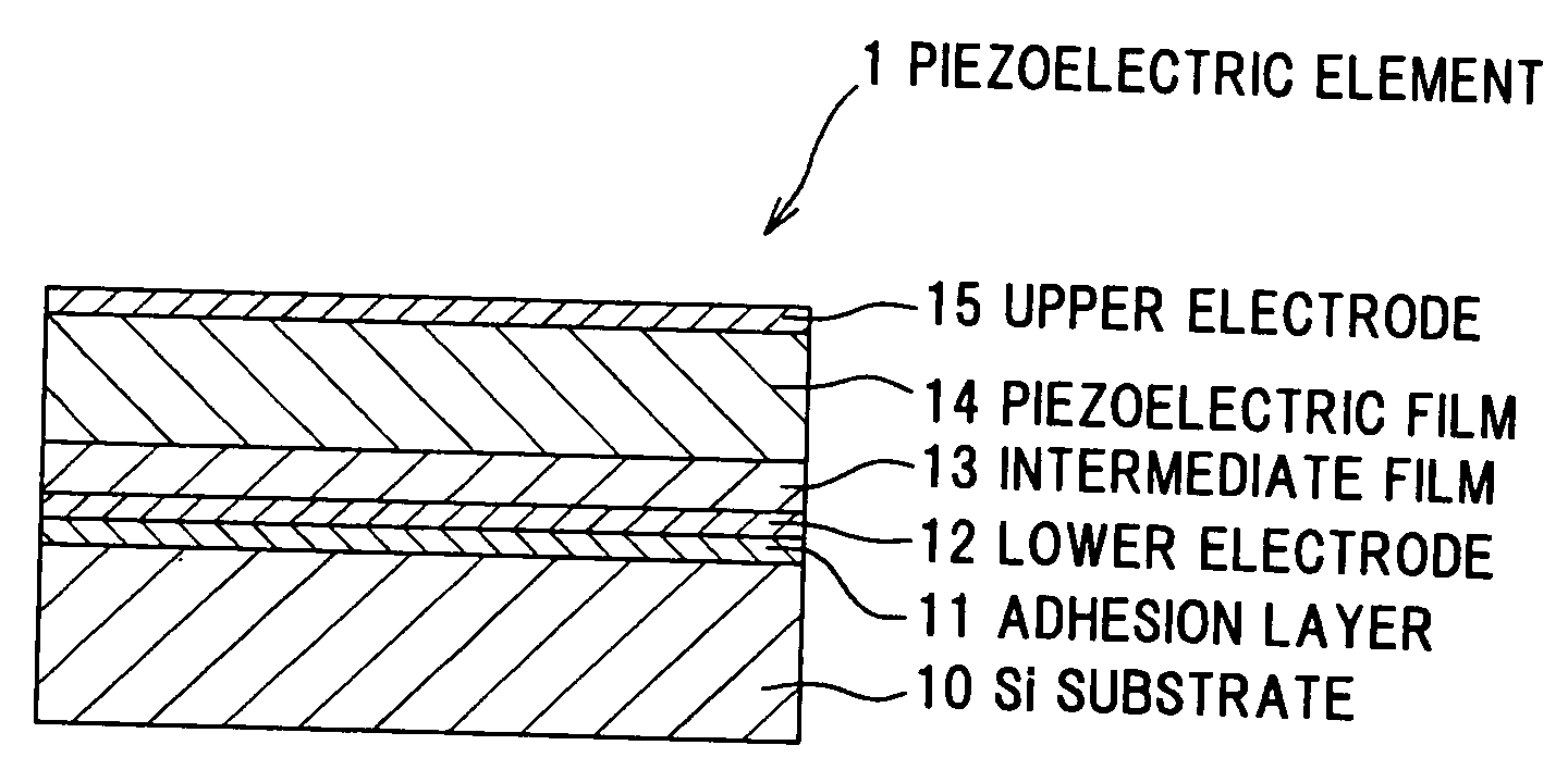
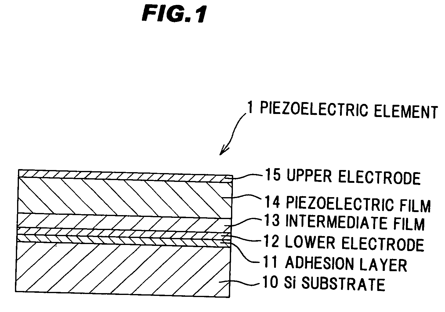
[0021]FIG. 1 is a cross sectional view of a piezoelectric element in a preferred embodiment according to the invention.

[0022]In the first preferred embodiment, a piezoelectric element 1 comprises a silicon (Si) substrate 10 having a plane orientation (100) as a substrate, an adhesion layer 11 as a part of a metallic layer formed on the Si substrate 10, a lower electrode 12 as a part of a metallic layer formed on the adhesion layer 11, an intermediate film 13 formed on the lower electrode 12, a piezoelectric film 14 formed as a piezoelectric thin film on the intermediate film 13, and an upper electrode 15 formed on the piezoelectric film 14 as shown in FIG. 1.

[0023]For instance, the Si substrate 10 is formed to have a substantially square shape of 20 mm×20 mm in plan view, and a thermally-oxidized film is formed on a surface of the Si substrate 10. The Si substrate 10 comprises a substrate with a thickness of 0.5 mm is used. Further, the adhesion layer 11 is provi...


PUM

PropertyMeasurementUnit
Lattice constantaaaaaaaaaa
Fractionaaaaaaaaaa
Lengthaaaaaaaaaa

Abstract

A piezoelectric film formed above a Si substrate. The piezoelectric film is formed of a potassium sodium niobate expressed by a general formula (K,Na)NbO3 with perovskite structure. A film thickness of the piezoelectric film is within a range from 0.3 μm to 10 μm. An intermediate film is formed between the Si substrate and the piezoelectric film. The intermediate film generates a stress in a compressive direction in the piezoelectric film.

Description

BACKGROUND OF THE INVENTION[0001]The present application is based on Japanese Patent Application No. 2007-241207, the entire contents of which are incorporated herein by reference.FIELD OF THE INVENTION[0002]The present invention relates to a piezoelectric element, particularly to a piezoelectric element having a piezoelectric thin film formed on a silicon (Si) substrate.RELATED ART[0003]A piezoelectric element having a piezoelectric material is used for an actuator or a sensor etc for a head of a high-precision and high-speed inkjet printer. A Pb(Zr1-xTix)O3 based perovskite-type ferroelectric substance (piezoelectric lead zirconium titanate: PZT) has been widely used as a piezoelectric material for forming such a piezoelectric element. However, since the PZT contains lead (Pb), it is desired to use a piezoelectric material containing no lead, i.e. a Pb-free piezoelectric material for a piezoelectric element from a consideration of environmental point of view. Further, it is desire...

Claims


Application Information

Patent Timeline
IPC IPC(8): B32B33/00H01L41/09H01L41/18H01L41/187H01L41/22H01L41/316H01L41/319H02N2/00
CPCH01L41/08Y10T428/265Y10T428/26H01L41/187H10N30/2042H10N30/8542H10N30/076H10N30/708
Inventor SHIBATA, KENJIOKA, FUMIHITO
Owner SUMITOMO CHEM CO LTD
Learn More