
Liquid crystal display driver and method thereof

a technology of liquid crystal display and driver, which is applied in the direction of electric digital data processing, instruments, computing, etc., can solve the problems of deteriorating linearity of output voltage, increasing power consumption, and affecting the linearity of analog output voltage for dacs, so as to achieve the effect of suppressing adverse effects on analog output voltag

Inactive Publication Date: 2006-08-08
IBM CORP
View PDF5 Cites 21 Cited by
  • Summary
  • Abstract
  • Description
  • Claims
  • Application Information

AI Technical Summary

Benefits of technology

[0013]In view of the technical problems described above, a feature of the present invention is to suppress adverse effects upon an analog output voltage due to switching depending on digital input data.
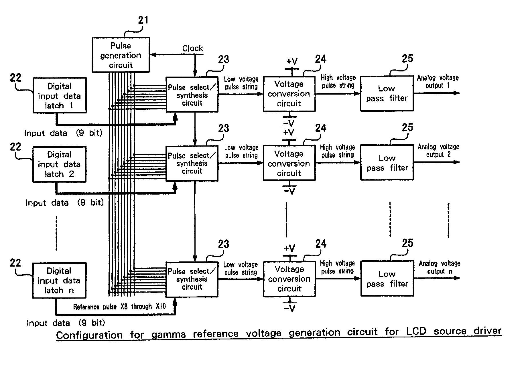
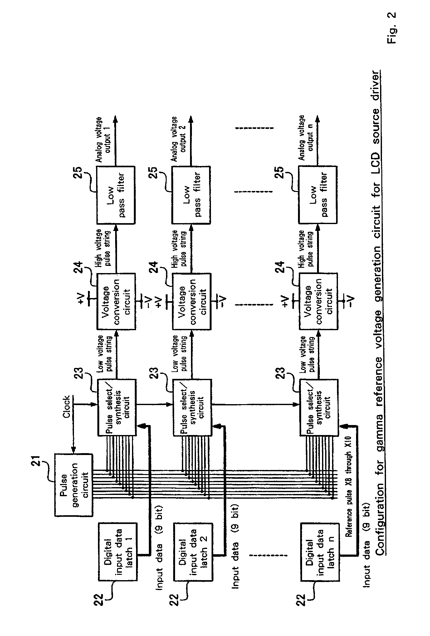
[0015]According to the present invention, the number of switching times for pulse strings generated is configured to be smooth and constant without a local peak with respect to digital input data. Namely, the present invention provides a liquid crystal display that includes a liquid crystal cells forming an image display area on a substrate and a driver for applying a voltage to the liquid crystal cells based on a reference voltage for gamma correction corresponding to digital input data. The driver, which is mounted on the substrate and is comprised of a plurality of driver ICs connected via signal lines, keeps the number of switching times for pulse strings per time unit constant for a predetermined range of the digital input data when generating the pulse strings with pulse densities corresponding to the digital input data.

Problems solved by technology

On the contrary, power consumption is increased due to the increase of frequency of the pulse string, and moreover the linearity of the output voltage is deteriorated because the number of switching times differs for pulse strings corresponding to each of digital input data.
This deteriorates the linearity of analog output voltage for DACs.
Moreover, if the values of resistors and capacitors used for integration circuit 205 are set to match with pulse strings with low frequencies (i.e., around 0 or 511 of digital input data), the frequency of pulse strings becomes too high around a medium value (256) of the digital input data, resulting in unwanted power consumption.

Method used


Image

  • Liquid crystal display driver and method thereof
  • Liquid crystal display driver and method thereof
  • Liquid crystal display driver and method thereof

Examples


Embodiment Construction

[0033]The predetermined range of digital input data may be, for example, the digital input data ranging from 128 to 384 given a 9-bit digital-analog conversion circuit. Such a predetermined range may vary depending on the number of divided bits (W).

[0034]In another aspect of the invention, there is provided a driver for use in a liquid crystal display, that is characterized by having no local peak in the number of switching times for pulse strings per time unit when generating the pulse strings with pulse densities corresponding to the digital input data.

[0035]In a further aspect of the invention, there is provided a driver for use in a liquid crystal display, that is characterized by obtaining a reference voltage for gamma correction using pulse density modulation (PDM) as well as obtaining an output voltage using pulse width modulation (PWM) for a predetermined range of the digital input data around a medium value when generating pulse strings corresponding to the digital input da...


PUM


Abstract

JP920010105US125 A liquid crystal display driver for applying a voltage to liquid crystal cells forming an image display area includes a pulse generation circuit for generating a plurality of reference pulses in which pulse generation densities are weighted, a pulse select / synthesis circuit for generating a pulse string by selecting and synthesizing necessary reference pulses on the basis of digital input data and the reference pulses and an integration circuit (low pass filter) for integrating the pulse string generated by the pulse select / synthesis circuit to output an analog voltage for gamma correction.

Description

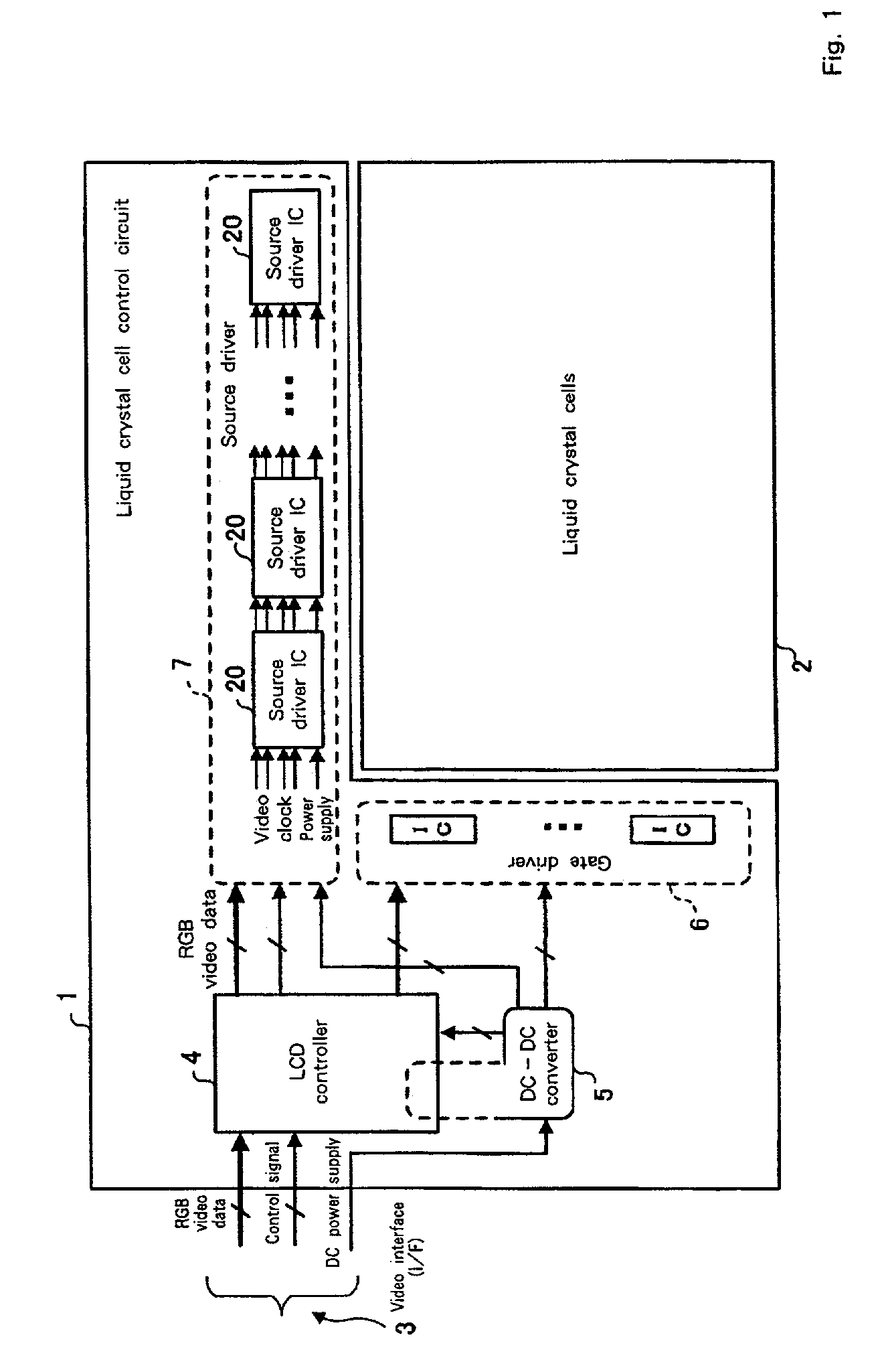
BACKGROUND OF THE INVENTION[0001]1. Field of the Invention[0002]The present invention relates to a liquid crystal display and pulse generation circuit for displaying images on the basis of input video signals, and more particularly to a liquid crystal display and pulse generation circuit in which the number of switching times for pulse strings is improved.[0003]2. Background of the Invention[0004]In general, when an image is displayed on a liquid crystal display (LCD), image signals are output from a graphics controller in a system unit or system part of a PC or the like via a video interface. An LCD controller LSI, which receives these image signals, supplies signals to each IC in a source driver (i.e., X driver, LCD driver) and gate driver (i.e., Y driver), and then a voltage is applied to each source electrode and each gate electrode in a TFT array arranged in a matrix fashion, thereby leading to displaying images.[0005]As a configuration employed in this LCD source driver, techn...

Claims


Application Information

Patent Timeline
IPC IPC(8): G09G3/36G09G5/10G02F1/133G09G3/20
CPCG09G3/3688G09G3/2007G09G2320/0276G09G2310/027
Inventor SAKAGUCHI, YOSHITAMISAKUMA, KATSUYUKI
Owner IBM CORP
Learn More