
Dental observation apparatus

a technology for observation apparatus and teeth, which is applied in the field of dental observation apparatus, can solve the problems of inconvenient inspection, inability to frequently perform inspection, and inability to detect very small caries at an early stage, etc., and achieves the effect of avoiding the formation of a large number of sclerosing sclerosing sclerosing sclerosing sclerosing sclerosing sclerosing sclerosing s

Inactive Publication Date: 2009-03-19
OLYMPUS CORP
View PDF10 Cites 92 Cited by
  • Summary
  • Abstract
  • Description
  • Claims
  • Application Information

AI Technical Summary

Benefits of technology

[0011]According to the present invention, when the illumination light including an infrared region is radiated from the irradiating unit to the tooth, the fluorescence is emitted from the caries portion present in the tooth, and in addition, the scattered light of the illumination light is generated from the whole tooth; hence, when the above two types of light are detected separately by the detecting unit, and the fluorescence image and the scattered light image are combined, a composite image including the whole tooth and the caries portion located therein can be obtained with high contrast.
[0036]Accordingly, the present invention affords advantages in that caries located at a position that cannot be directly viewed, such as one of the adjacent surfaces between teeth, can be observed with high contrast, and in that the spread and the degree of invasion of the caries can be observed.

Problems solved by technology

In visual inspection, it is inconveniently difficult to confirm very small caries at an early stage and / or caries located at a position that cannot be directly viewed, such as one of the adjacent surfaces between teeth.
In addition, one problem with x-ray inspection is that inspection cannot be frequently performed because x-ray exposure occurs.
However, the technique disclosed in U.S. Pat. No. 6,201,880 has drawback that, since white light which is liable to be influenced by scattering inside teeth is used, caries occurring at a position that cannot be directly viewed from the surface of teeth cannot be observed with high contrast.

Method used


Image

  • Dental observation apparatus
  • Dental observation apparatus
  • Dental observation apparatus

Examples


first embodiment

[0070]A dental observation apparatus 1 according to the present invention will be described with reference to FIGS. 1 to 7.

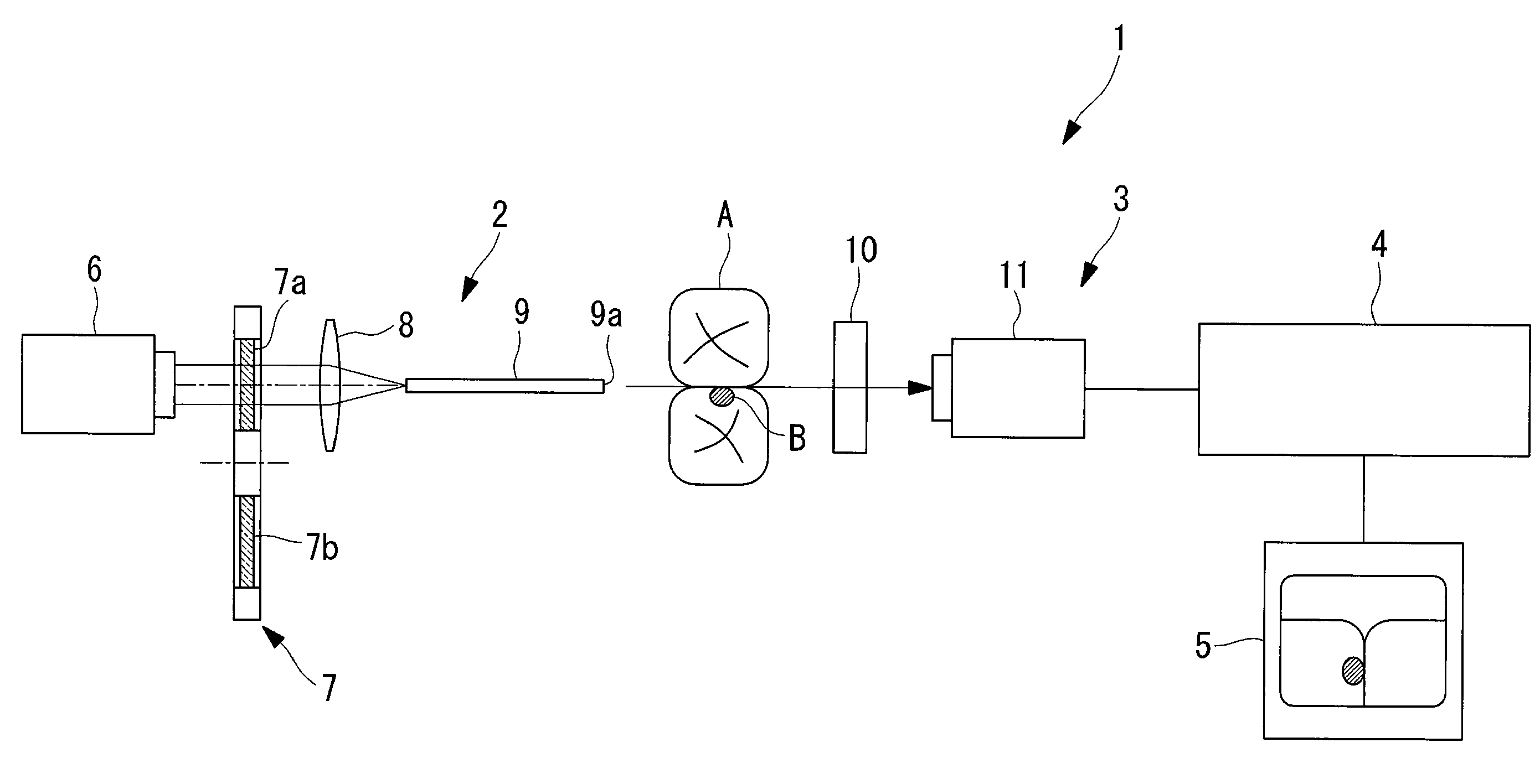
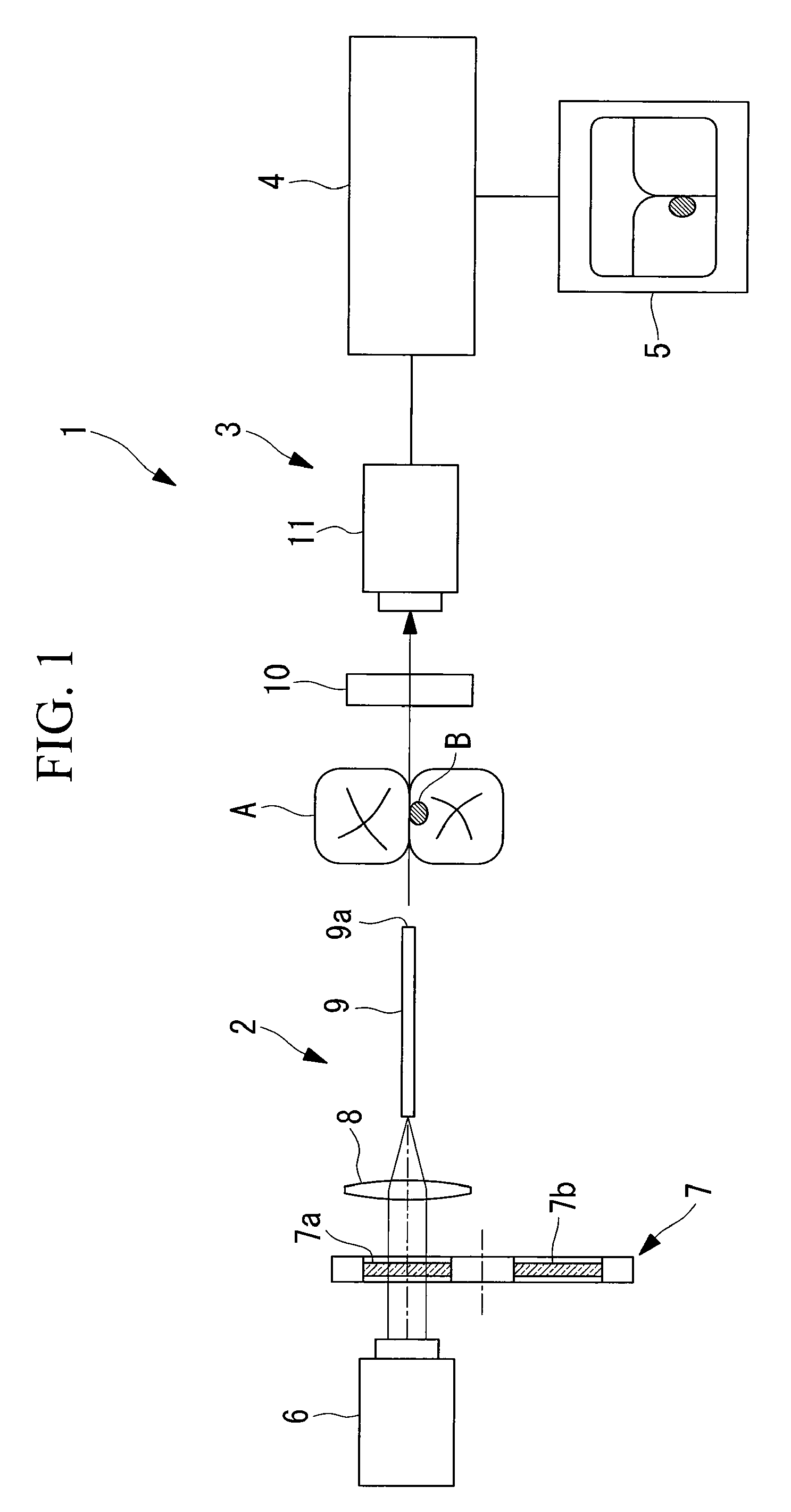
[0071]The dental observation apparatus 1 according to this embodiment has, as shown in FIG. 1, an irradiating unit 2 irradiating a tooth A with illumination light including an infrared region, a detecting unit 3 detecting light emitted from a caries portion B of the tooth A by irradiation with the illumination light from the irradiating unit 2, an image processing unit 4 forming an image based on the intensity of light detected by the detecting unit 3, and a display unit 5 displaying the image formed by the image processing unit 4.

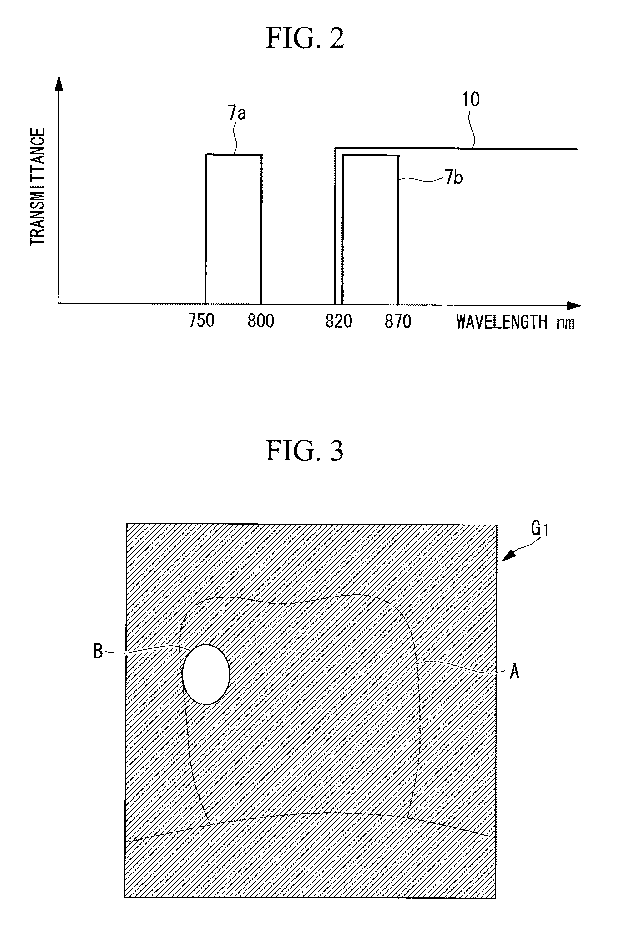
[0072]The irradiating unit 2 includes a light source 6 generating light in a wide wavelength band, a rotary filter 7 which includes two types of filters 7a and 7b selecting two wavelength bands (such as 750 to 800 nm and 820 to 870 nm) in different infrared regions from light emitted from the light source 6, as shown in FIG. 2, a focus...

second embodiment

[0108]Next, a dental observation apparatus 20 according to the present invention will be described with reference to FIGS. 21 to 29.

[0109]In addition, in the description of this embodiment, elements and the like corresponding to those of the dental observation apparatus 1 of the above first embodiment are designated by the same reference numerals as those described above, and a description thereof is omitted.

[0110]As shown in FIGS. 21 and 22, the dental observation apparatus 20 of this embodiment has two light source 21 and 22 generating first illumination light L, and second illumination light L2, respectively, which have different wavelength bands; optical fibers (light guiding members) 23 and 24 guiding the illumination light L1 and the illumination light L2 from the light sources 21 and 22, respectively; a first polarizing plate (first polarizing member) 25 disposed between the teeth A and front end surfaces (first irradiating portion and second irradiating portion) 23a and 24a ...


PUM


Abstract

Caries located at a position that cannot be directly viewed, such as one of the adjacent surfaces between teeth, can be observed with high contrast, and the spread and the degree of invasion of the caries can be observed. A dental observation apparatus has: an irradiating unit radiating illumination light including an infrared region; a detecting unit separately detecting fluorescence generated from a caries portion by irradiation with the illumination light and scattered light of the illumination light at the tooth; and an image processing unit which forms a fluorescence image based on the fluorescence detected by the detecting unit, which forms a scattered light image capable of identifying a boundary between an enamel layer and a dentine layer, the layers having different scattering properties, based on the intensity of the scattered light detected by the detecting unit, and which combines the fluorescence image and the scattered light image.

Description

BACKGROUND OF THE INVENTION[0001]1. Field of the Invention[0002]The present invention relates to a dental observation apparatus.[0003]This application is based on Japanese Patent Applications, No. 2007-241363 and No. 2008-181574, the content of which is incorporated herein by reference.[0004]2. Description of Related Art[0005]Heretofore, dental caries is generally recognized by visual inspection or x-ray inspection by a dentist. In visual inspection, it is inconveniently difficult to confirm very small caries at an early stage and / or caries located at a position that cannot be directly viewed, such as one of the adjacent surfaces between teeth. In addition, one problem with x-ray inspection is that inspection cannot be frequently performed because x-ray exposure occurs.[0006]In order to avoid the above inconveniences to detect dental caries at an early stage and to observe caries located at a position which cannot be easily viewed, there is a known technique in which teeth are irrad...

Claims


Application Information

Patent Timeline
Patent Type & Authority Applications(United States)
IPC IPC(8): A61C19/06
CPCA61B5/0088G01N21/64A61B2562/0238
Inventor KUMADA, YOSHIYUKIKANEKO, MAMORUYOSHIDA, KAZUHIRO
Owner OLYMPUS CORP
Features
  • Generate Ideas
  • Intellectual Property
  • Life Sciences
  • Materials
  • Tech Scout
  • Unparalleled Data Quality
  • Higher Quality Content
  • 60% Fewer Hallucinations
Learn More