Everting Heart Valve

a heart valve and endovascular technology, applied in the field of endovascular replacement of heart valves, can solve the problems of heart failure, heart attack, stroke, adverse reactions to anesthesia medications, and high invasiveness of valve replacement surgery

Active Publication Date: 2009-03-19
BOSTON SCI SCIMED INC
View PDF103 Cites 408 Cited by
  • Summary
  • Abstract
  • Description
  • Claims
  • Application Information

AI Technical Summary

Problems solved by technology

Valve replacement surgery is a highly invasive operation with significant concomitant risk.
Risks include bleeding, infection, stroke, heart attack, arrhythmia, renal failure, adverse reactions to the anesthesia medications, as well as sudden death.
Standard self-expanding systems have very poor accuracy in deployment, however.
It is therefore often impossible to know where the ends of the stent will be with respect to the native valve, the coronary ostia and the mitral valve.
Visualization prior to final and irreversible deployment cannot be done with standard self-expanding systems, however, and the replacement valve is often not fully functional before final deployment.
Another drawback of prior art self-expanding replacement heart valve systems is their lack of radial strength.
However when the stent has a valve fastened inside it, as is the case in aortic valve replacement, the anchoring of the stent to vessel walls is significantly challenged during diastole.
Moreover, a self-expanding stent without sufficient radial force will end up dilating and contracting with each heartbeat, thereby distorting the valve, affecting its function and possibly migrating and dislodging completely.
Simply increasing strut thickness of the self-expanding stent is not a practical solution as it runs the risk of larger profile and / or plastic deformation of the self-expanding stent.

Method used


Image

  • Everting Heart Valve
  • Everting Heart Valve
  • Everting Heart Valve

Examples


Embodiment Construction

[0063]While preferred embodiments of the present invention have been shown and described herein, it will be obvious to those skilled in the art that such embodiments are provided by way of example only. Numerous variations, changes, and substitutions will now occur to those skilled in the art without departing from the invention. It should be understood that various alternatives to the embodiments of the invention described herein may be employed in practicing the invention. For example, for the two-part locking mechanisms described hereinafter, it will be apparent that the locations of the male and female elements may be reversed. It is intended that the following claims define the scope of the invention and that methods and structures within the scope of these claims and their equivalents be covered thereby.

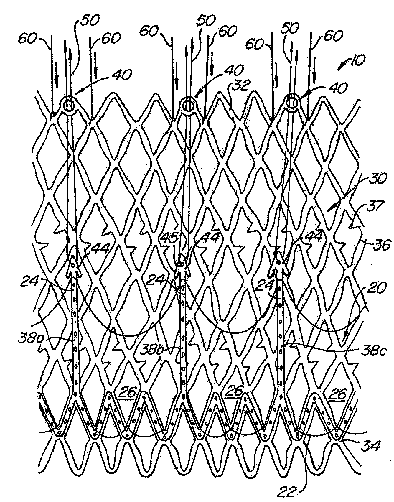
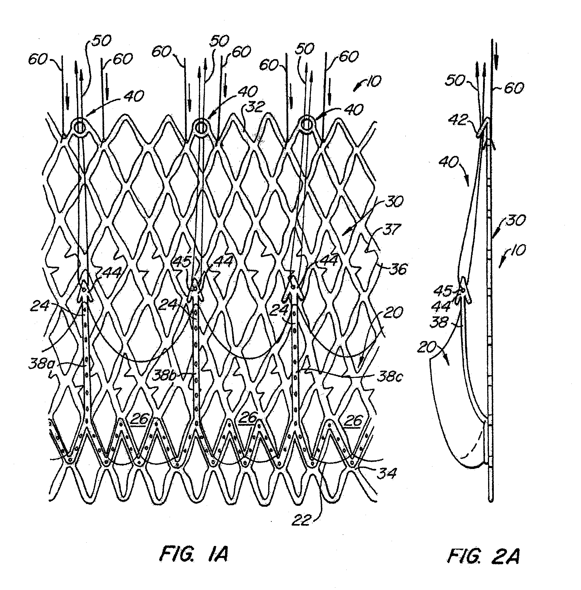
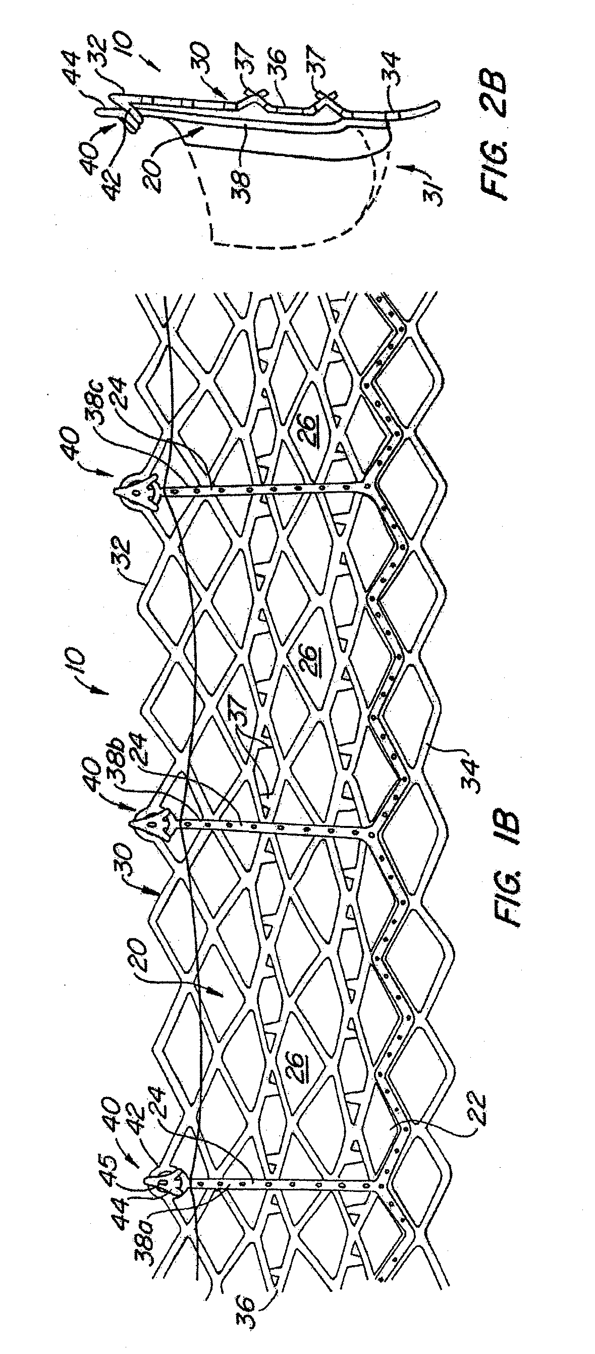
[0064]With reference now to FIGS. 1-4, a first embodiment of replacement heart valve apparatus in accordance with the present invention is described, including a method of acti...


PUM


Abstract

The present invention provides methods and apparatus for endovascularly replacing a patient's heart valve. The apparatus includes a replacement valve and an expandable anchor configured for endovascular delivery to a vicinity of the patient's heart valve. In some embodiments, the replacement valve is adapted to wrap about the anchor, for example, by everting during endovascular deployment. In some embodiments, the replacement valve is not connected to expandable portions of the anchor. In some embodiments, the anchor is configured for active foreshortening during endovascular deployment. In some embodiments, the anchor includes expandable lip and skirt regions for engaging the patient's heart valve during deployment. In some embodiments, the anchor comprises a braid fabricated from a single strand of wire. In some embodiments, the apparatus includes a lock configured to maintain anchor expansion. The invention also includes methods for endovascularly replacing a patient's heart valve. In some embodiments, the method includes the steps of endovascularly delivering a replacement valve and an expandable anchor to a vicinity of the heart valve, wrapping at least a portion of the replacement valve about the anchor, and expanding the anchor to a deployed configuration.

Description

CROSS-REFERENCE TO RELATED APPLICATION[0001]This application is a continuation of pending U.S. application Ser. No. 10 / 870,340, filed Jun. 16, 2004, entitled “Everting Heart Valve”, the disclosure of which is incorporated by reference in its entirety as if fully set forth herein.BACKGROUND OF THE INVENTION[0002]The present invention relates to methods and apparatus for endovascularly replacing a heart valve. More particularly, the present invention relates to methods and apparatus for endovascularly replacing a heart valve with a replacement valve and an expandable and retrievable anchor. The replacement valve preferably is not connected to the expandable anchor and may be wrapped about an end of the anchor, for example, by everting during endovascular deployment.[0003]Heart valve surgery is used to repair or replace diseased heart valves. Valve surgery is an open-heart procedure conducted under general anesthesia. An incision is made through the patient's sternum (sternotomy), and ...

Claims


Application Information

Patent Timeline
Patent Type & Authority Applications(United States)
IPC IPC(8): A61F2/24A61F2/90
CPCA61F2/2418A61F2/2433A61F2/2436A61F2/2439A61F2220/0016A61F2230/0078A61F2220/0058A61F2220/0075A61F2230/005A61F2230/0054A61F2230/0065A61F2220/005A61F2220/0033A61F2/2412
Inventor SALAHIEH, AMRHAUG, ULRICH R.VALENCIA, HANS F.GESHLIDER, ROBERT A.SAUL, TOMMOREJOHN, DWIGHT P.MICHLITSCH, KENNETH J.
Owner BOSTON SCI SCIMED INC
Why Eureka
Try Eureka