Temporary arterial shunt and method

a technology of shunt and catheter, which is applied in the field of temporary catheter, can solve the problems of myocardial infarction, difficult to remove the catheter following, and the interruption of blood flow in the recipient artery may be dangerous to the patient, and achieve the effect of improving fluid-tight sealing of the catheter

Inactive Publication Date: 2005-11-22
ORIGIN MEDSYST +1
View PDF38 Cites 175 Cited by
  • Summary
  • Abstract
  • Description
  • Claims
  • Application Information

AI Technical Summary

Benefits of technology

[0004]In accordance with an embodiment of the present invention, a shunt is formed of a coiled strand, with a loop of the strand extending out of the center of the formed shunt. A tube is positioned over the center loop against the shunt to aid in removing the shunt by uncoiling the coiled strand for retrieval through the tube. The distal ends of the shunt may contain bulbous portions formed out of the strand to enhance fluid-tight sealing of the shunt within the inner walls. Alternatively, the coiled strand may form a tapered shunt, with one end of greater diameter than the other end.

Problems solved by technology

However, interruption of blood flow in the recipient artery may be dangerous to the patient.
Ischemia to the heart during coronary artery bypass may result in myocardial infarction.
Similarly, ischemia to the brain during carotid endarterectomy may result in stroke.
Presently, it is difficult to remove a shunt following its use.
Shunt removal is a delicate process, and it may be difficult to perform without disrupting the anastomosis being formed.
The anastomotic suture may be broken, or tension on the suture may cause it to cut through the arterial wall.

Method used


Image

  • Temporary arterial shunt and method
  • Temporary arterial shunt and method
  • Temporary arterial shunt and method

Examples


Embodiment Construction

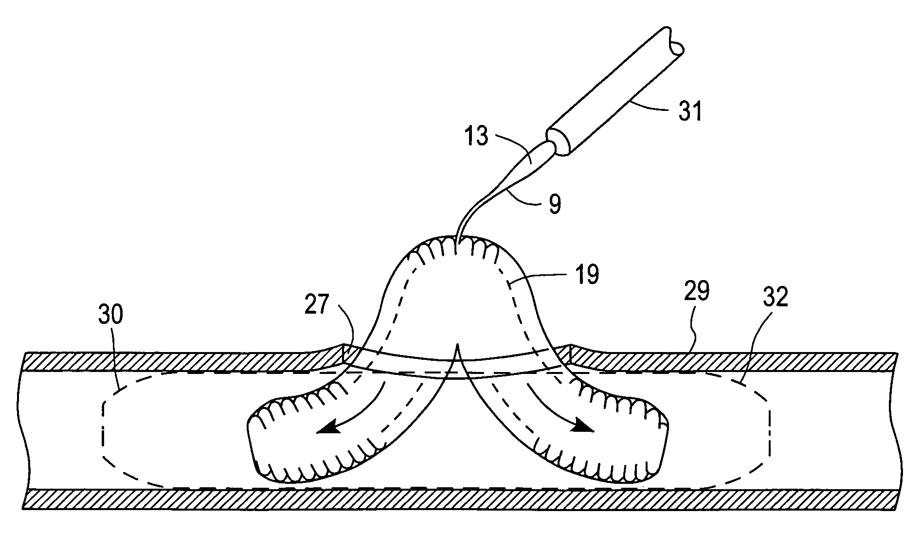
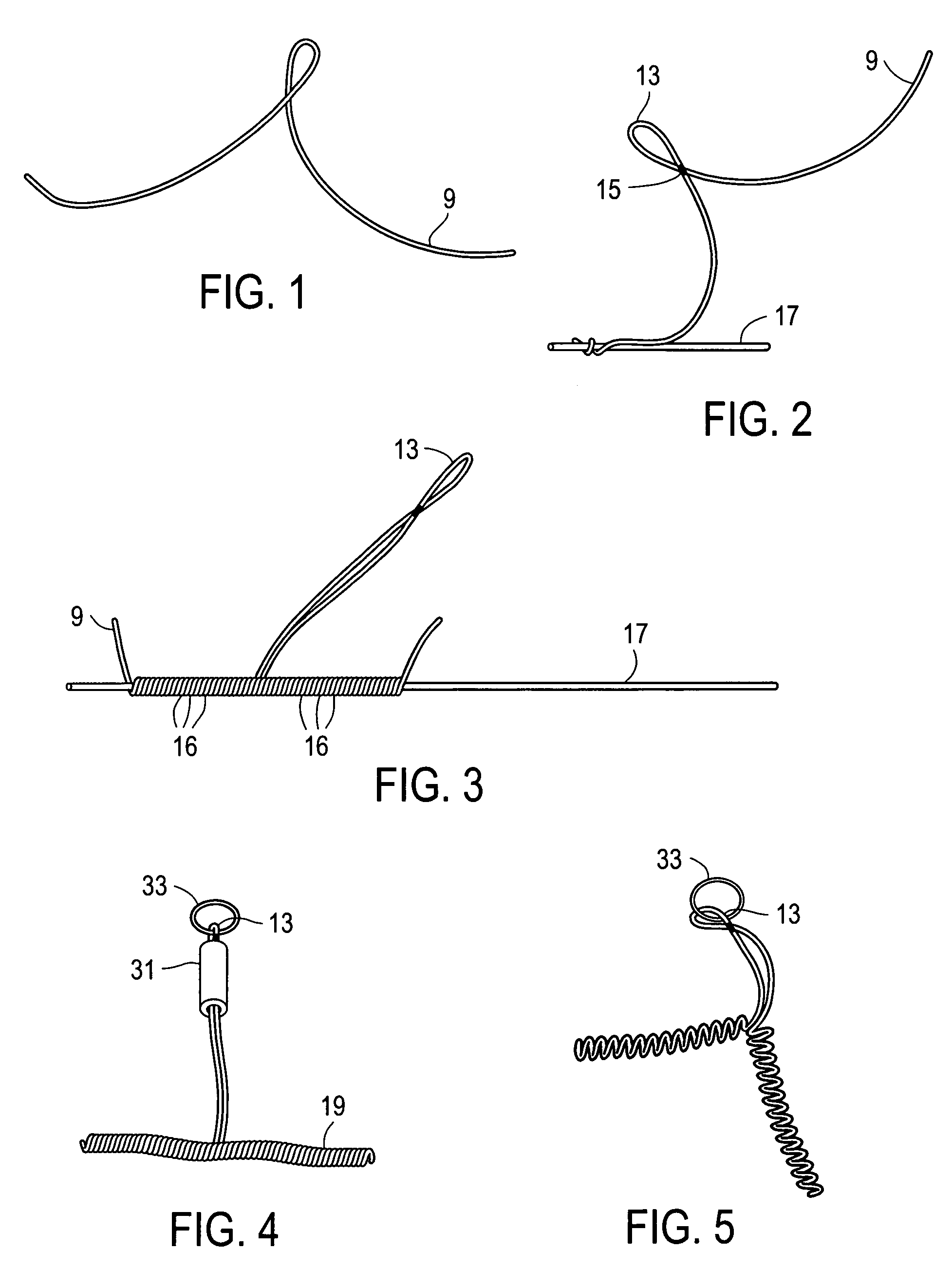
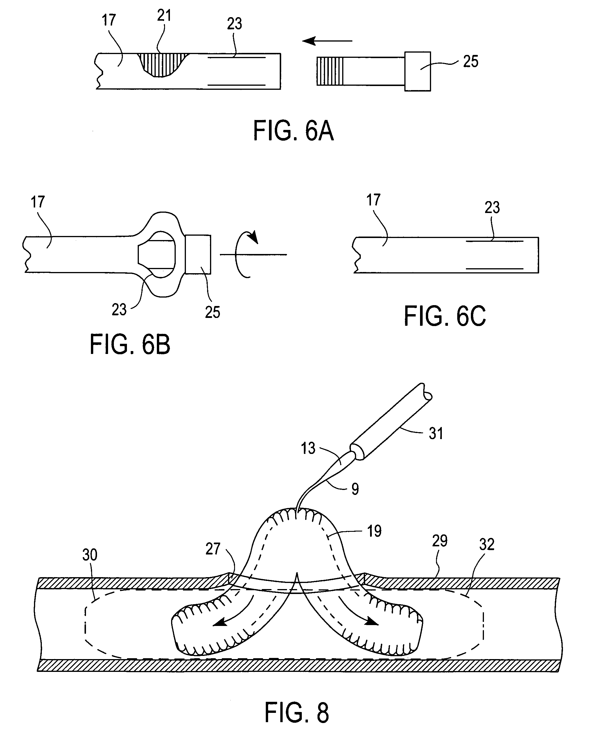
[0014]Referring now to FIGS. 1–4, there is shown an embodiment of the present invention in which a tubular conduit for use as an arterial shunt is formed as a coil including a plurality of substantially contiguous convolutes 16 of an elongated strand 9 that may be coated with a bioinert and preferably thermoplastic polymer. The strand 9 is wound on a mandrel 17 that has a substantially constant diameter between the ends thereof, with a protruding loop 13 formed intermediate the ends. The strand 9 is constructed from a length of suture or wire that is coated with a material such as polyvinyl chloride, polyurethane, silicone rubber, or the like. The center of the length of strand 9 is formed into the loop 13 of length approximately 5 cm. The two strands at the bottom of the loop 13 may be held together by a tie 15 such as a band heat-sealed to the strands, or by a length of heat shrink tubing, or by a suture winding, or held together by adhesive, or by welding a length of adjacent str...


PUM


Abstract

Surgical construction or bypass grafting of a target vessel includes method and instrumentation and apparatus for forming and inserting a fluid-impervious tubular conduit including a central protrusion through an aperture in the vessel to form a fluid-conducting shunt past the aperture. An anastomosis over the aperture is partially completed with the protrusion of the tubular conduit extending through the partial anastomosis. A removal tube is disposed over the protrusion for applying tensile force thereto relative to the tubular conduit for dissembling the tubular conduit along a continuous path for removal as a single strand from the vessel through the tube and aperture and the partial anastomosis prior to completion of the procedure.

Description

FIELD OF THE INVENTION[0001]This invention relates to temporary conduits for use in vascular surgical procedures, and more particularly to a temporary shunt for easy insertion into, and removal from, a target vessel in a living body.BACKGROUND OF THE INVENTION[0002]During arterial reconstruction or bypass procedures, the target artery is generally clamped proximal and distal to an anastomotic site for a brief interval to provide a blood-free field for performing the anastomosis. However, interruption of blood flow in the recipient artery may be dangerous to the patient. Ischemia to the heart during coronary artery bypass may result in myocardial infarction. Similarly, ischemia to the brain during carotid endarterectomy may result in stroke. Consequently, surgeons often place an arterial shunt in the artery undergoing reconstruction, to avoid the potential for ischemic complications. The arterial shunt is a flexible tube that is inserted into the arteriotomy. The outer diameter of th...

Claims


Application Information

Patent Timeline
Patent Type & Authority Patents(United States)
IPC IPC(8): A61F11/00A61B17/03A61M25/00A61M5/00A61B17/08A61B17/11A61B17/12A61F2/06
CPCA61B17/11A61B17/12045A61B2017/12127A61F2/064
Inventor CHIN, ALBERT K.
Owner ORIGIN MEDSYST
Why Eureka
Try Eureka