
Multiprocessor system

a multi-processor system and multi-processor technology, applied in the direction of micro-instruction address formation, memory address/allocation/relocation, instruments, etc., can solve the problems of multi-processor system, performance of the entire system is not so improved but saturated, and memory load is imposed on the increase in the number of processors

Inactive Publication Date: 2009-03-19
RICOH KK
View PDF5 Cites 114 Cited by
  • Summary
  • Abstract
  • Description
  • Claims
  • Application Information

AI Technical Summary

Benefits of technology

[0009]It is an object of the present invention to at least

Problems solved by technology

However, in the tightly-coupled multiprocessor system, a larger load is imposed on the memory as the number of processors increases.
Therefore, although the performance of the entire system is improved to some extent according to the increase in the number of processors, even if the number of processors is further increased, the performance of the entire system is not so improved but saturated because of difficulty in accessing the memory.
In other words, the tightly-coupled multiprocessor system is suitable for a relatively small-size system but is not adaptable to a large-size multiprocessor system mounted with one-hundred or more processors.
However, in the loosely-coupled multiprocessor system, a communication band and a delay time (latency) among the processors affect the performance of the system.
However, Ethernet has latency during communication.
Further, a load of protocol processing such as TCP / IP in performing communication is heavy.
If latency is long during communication, for example, when data is frequently exchanged among the processors, a communication overhead increases and the performance of the entire system falls.
The heavy load of the protocol processing means that the precious performance of a CPU is wastefully consumed for processing other than a primary object of the CPU (e.g., simulation calculation).
However, interface cards for using InifiBand and Myrinet are extremely expensive because the interface cards are high in function and performance compared with those for Ethernet.
Therefore, InifiBand and Myrinet are not often adopted in multiprocessor systems required to be reduced in cost.
However, because InifiBand and Myrinet are merely high-speed communication means, it is rather difficult to realize a shared memory function on these interfaces.
As a result, development efficiency for the software falls.

Method used


Image

  • Multiprocessor system
  • Multiprocessor system
  • Multiprocessor system

Examples


Embodiment Construction

[0057]Exemplary embodiments of the present invention are explained in detail below with reference to the accompanying drawings.

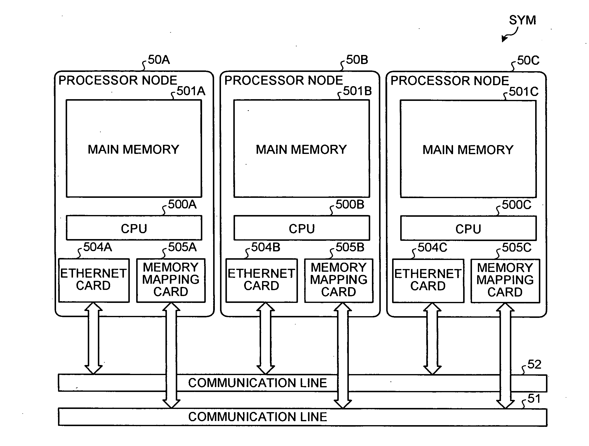
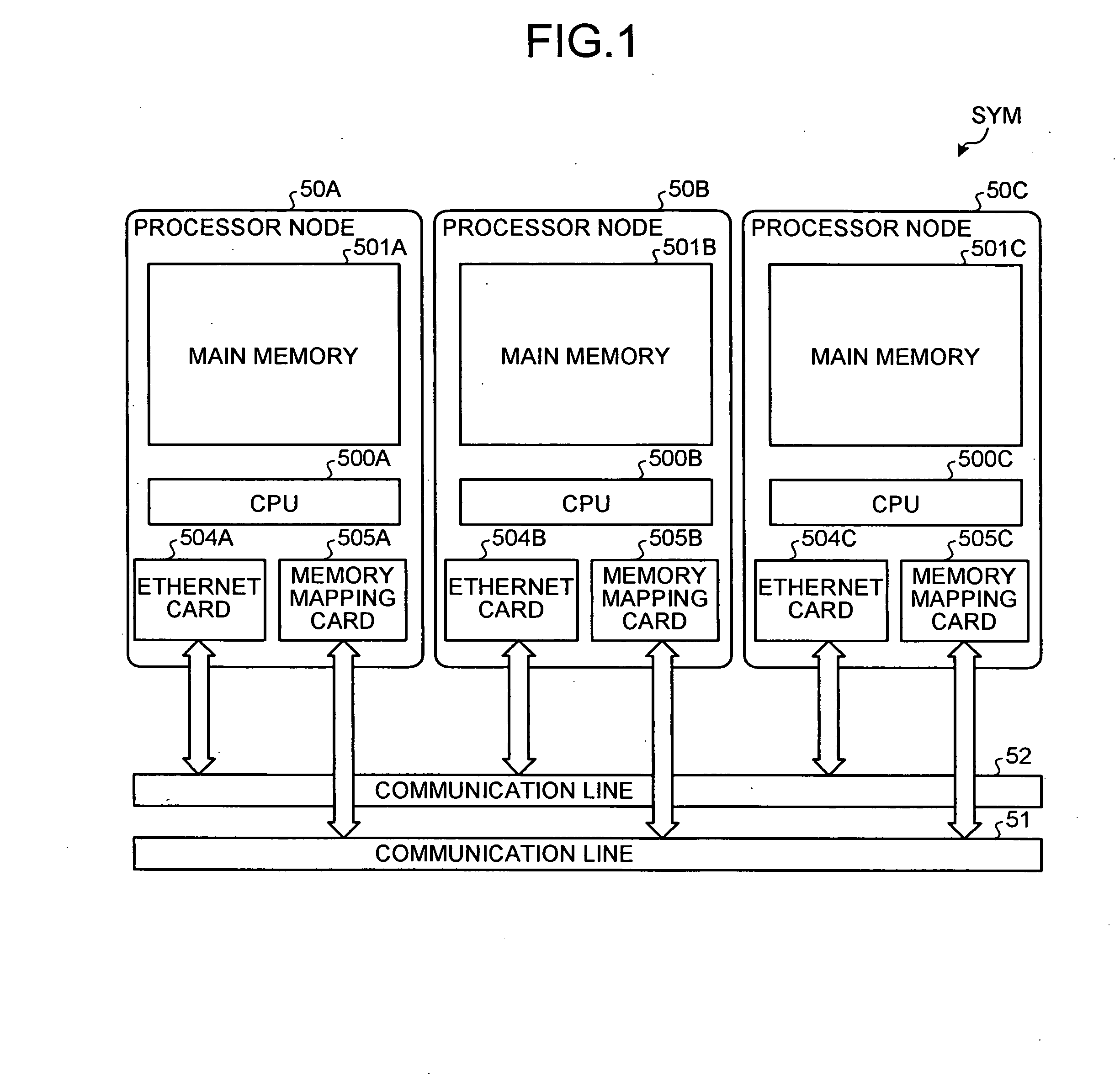
[0058]FIG. 1 is a diagram of a configuration of a multiprocessor system of a shared memory type according to an embodiment of the present invention. In a multiprocessor system SYM according to the embodiment, for example, three processor nodes 50A to 50C are connected to one another via a communication line 51 and a communication line 52. The processor node 50A includes a pair of a central processing unit (CPU) 500A and a main memory 501A, an Ethernet card 504A, and a memory mapping card 505A. The processor node 50A communicates with the other processor nodes 50B and 50C via the Ethernet card 504A and the communication line 52 or via the Ethernet card 504A and the communication line 51. The processor nodes 50C and 50C have the same configuration and perform communication in the same manner as the processor node 50A. The processor node 50A functions as a root...


PUM


Abstract

A memory mapping unit requests allocation of a remote memory to memory mapping units of other processor nodes via a second communication unit, and requests creation of a mapping connection to a memory-mapping managing unit of a first processor node via the second communication unit. The memory-mapping managing unit creates the mapping connection between a processor node and other processor nodes according to a connection creation request from the memory mapping unit, and then transmits a memory mapping instruction for instructing execution of a memory mapping to the memory mapping unit via a first communication unit of the first processor node.

Description

CROSS-REFERENCE TO RELATED APPLICATIONS[0001]The present application claims priority to and incorporates by reference the entire contents of Japanese priority document 2007-240025 filed in Japan on Sep. 14, 2007.BACKGROUND OF THE INVENTION[0002]1. Field of the Invention[0003]The present invention relates to loosely-coupled multiprocessor systems in which a plurality of processors having memories, in which memory spaces independent from one another are configured, are connected.[0004]2. Description of the Related Art[0005]Conventionally, there is a tightly-coupled multiprocessor system in which a plurality of processors share a main memory. Such a multiprocessor system can be configured at relatively low cost by adopting a processor applicable to a symmetric multi processing configuration (SMP) such as an x86 CPU of Intel Corporation and Advance Micro Devices, Inc. The processor is often adopted in a system that is not only required to be excellent in performance but also required to...

Claims


Application Information

Patent Timeline
IPC IPC(8): G06F12/02
CPCG06F12/0692
Inventor MOTOHASHI, HIROOMI
Owner RICOH KK
Learn More