
Muffler

a muffler and muffler body technology, applied in the field of mufflers, can solve the problems of undesirable backpressure of the muffler when reversing, and achieve the effect of reducing the backpressure of the muffler

Inactive Publication Date: 2009-03-26
FCA US +1
View PDF14 Cites 46 Cited by
  • Summary
  • Abstract
  • Description
  • Claims
  • Application Information

AI Technical Summary

Problems solved by technology

Exhaust systems typically muffle noise produced by combustion processes within engines.
Reflection mufflers may produce undesirable backpressure.

Method used


Image

  • Muffler
  • Muffler
  • Muffler

Examples


Embodiment Construction

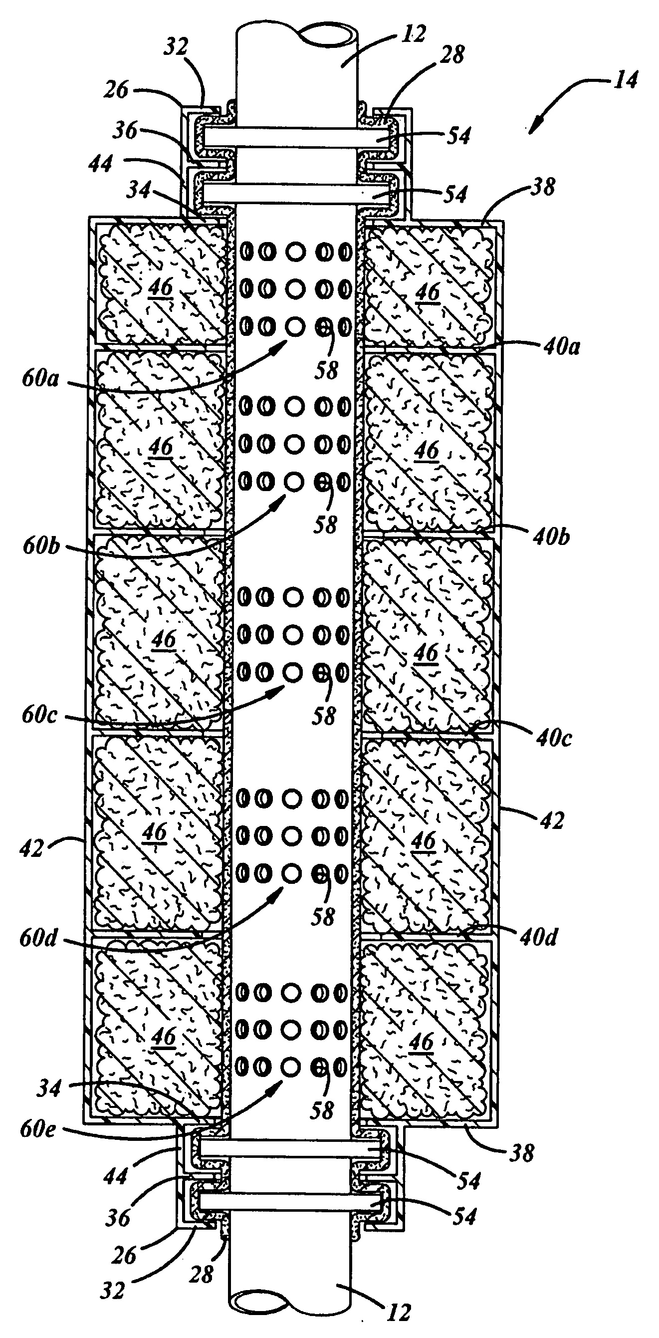
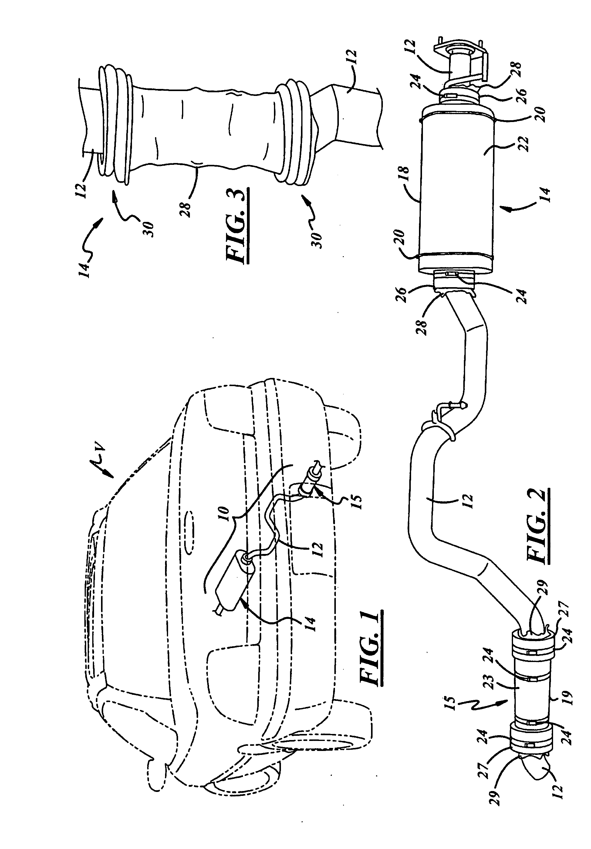
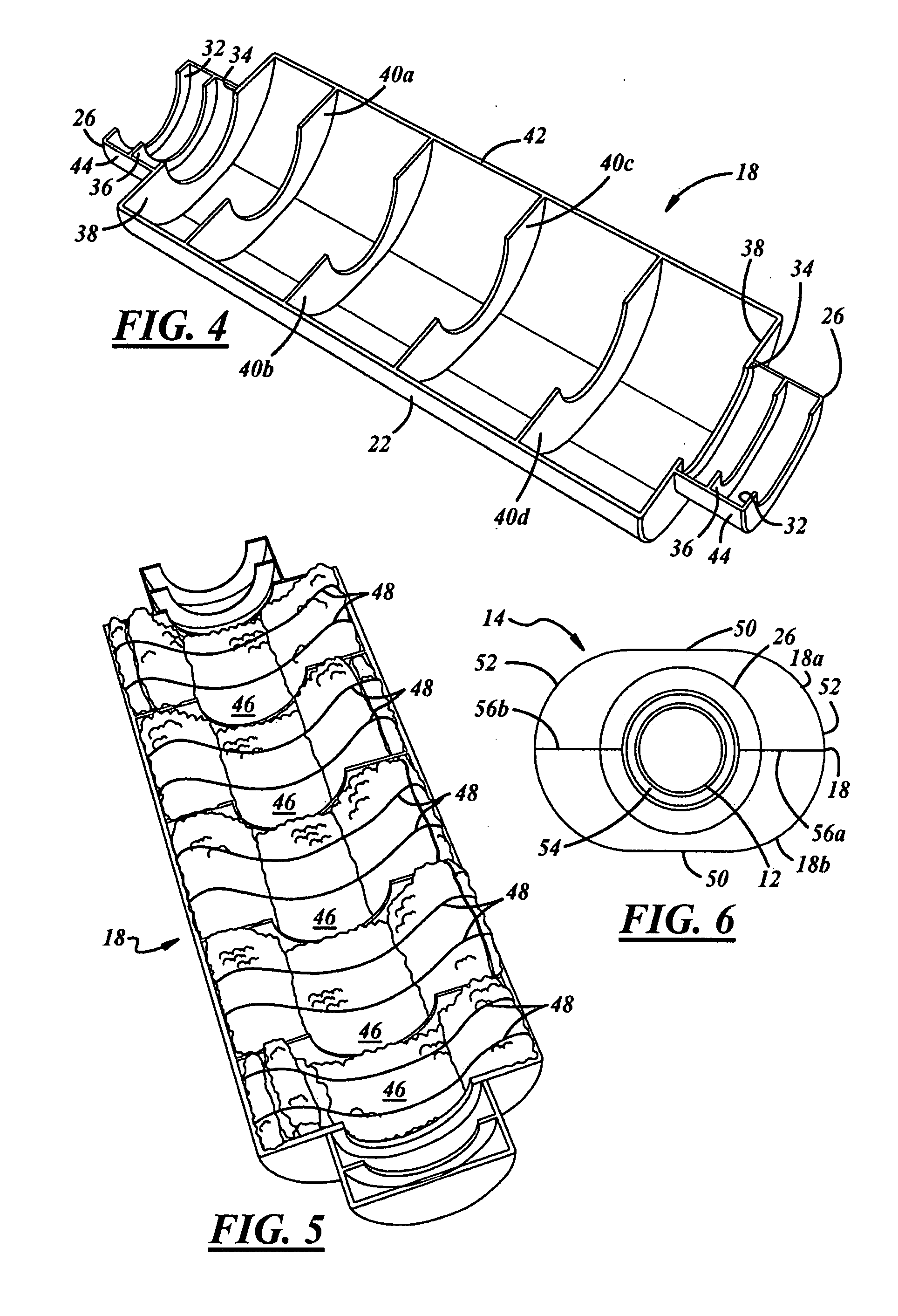
[0018]Referring in more detail to the drawings, FIG. 1 illustrates a schematic diagram of an exemplary vehicle V including an exhaust system 10, which is partially shown. The exhaust system 10 includes an exhaust pipe 12 and may include one or more mufflers including a first muffler 14 and / or a second muffler 15 downstream of the first muffler 14. The exhaust system 10 may be suspended or otherwise carried by the vehicle V in any suitable fashion. The mufflers 14, 15 may be used on other equipment besides motor vehicles.

[0019]Referring now to FIG. 2, the exhaust pipe 12 may be any type of conduit suitable for use in an exhaust system. For example, the exhaust pipe 12 may be metallic or at least partially composed of metal, for example, aluminized steel. The exhaust pipe 12 also may be a continuous component from an upstream side of the first muffler 14 to a downstream side of the second muffler 15 or may instead be constructed from a plurality of individual pipes in any suitable man...


PUM


Abstract

An absorption muffler includes a metallic exhaust pipe including a plurality of perforations, a polymeric housing carried by the exhaust pipe and enclosing the plurality of perforations, and including axially opposed ends. Thermal insulation is carried radially between the exhaust pipe and the polymeric housing and axially between the axially opposed ends inclusive thereof. Acoustic insulation is carried between the thermal insulation and the polymeric housing.

Description

CROSS REFERENCE TO RELATED APPLICATION[0001]This application claims the benefit of U.S. Provisional Patent Application Ser. No. 60 / 975,342, filed Sep. 26, 2007.FIELD OF THE INVENTION[0002]The present invention relates generally to engine exhaust systems, and more particularly to mufflers that attenuate engine exhaust acoustics.BACKGROUND OF THE INVENTION[0003]Exhaust systems typically muffle noise produced by combustion processes within engines. At a minimum, a typical exhaust system usually includes an exhaust pipe to carry engine exhaust gases and sound away from the engine, and a muffler to attenuate the sound propagated through the exhaust pipe. Mufflers include two general types according to the mode by which noise is attenuated. Mufflers that attenuate noise by reflection of sound waves are called reactive or reflection mufflers. Mufflers that attenuate noise by absorption of sound waves are known as dissipative or absorption mufflers.[0004]Reflection mufflers are particularly...

Claims


Application Information

Patent Timeline
Patent Type & Authority Applications(United States)
IPC IPC(8): F01N1/24
CPCF01N1/24F01N13/14F01N2310/02F01N13/1805F01N13/1827F01N13/16
Inventor SIKES, TIMOTHYGAERTNER, UDO
Owner FCA US
Learn More