Efuse system and testing method thereof

Inactive Publication Date: 2009-03-26
UNITED MICROELECTRONICS CORP
View PDF9 Cites 14 Cited by
  • Summary
  • Abstract
  • Description
  • Claims
  • Application Information

AI Technical Summary

Benefits of technology

[0025]In the present invention, simulations are performed on a plurality of eFuse systems composed of different device components or supplied with different voltages at a plurality of temperatures. An offset resistance is t

Problems solved by technology

However, the difference of the resistances between the eFuses in the program state and non-program state is quite close and the eFuse element in the sensing circuit of t

Method used


Image

  • Efuse system and testing method thereof
  • Efuse system and testing method thereof
  • Efuse system and testing method thereof

Examples


Embodiment Construction

[0033]Reference will now be made in detail to the present preferred embodiments of the invention, examples of which are illustrated in the accompanying drawings. Wherever possible, the same reference numbers are used in the drawings and the description to refer to the same or like parts.

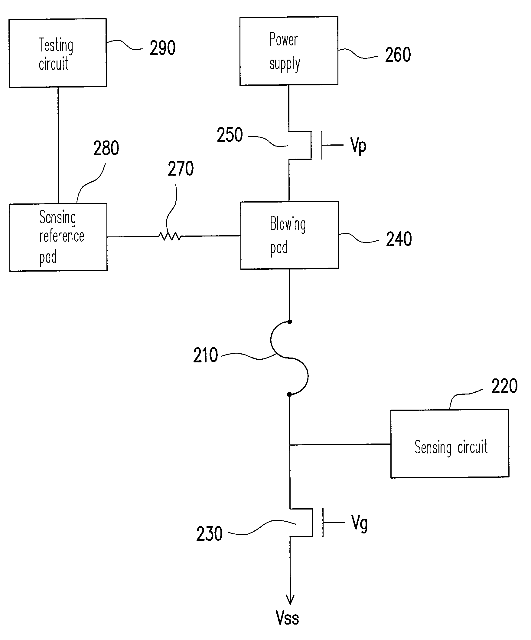
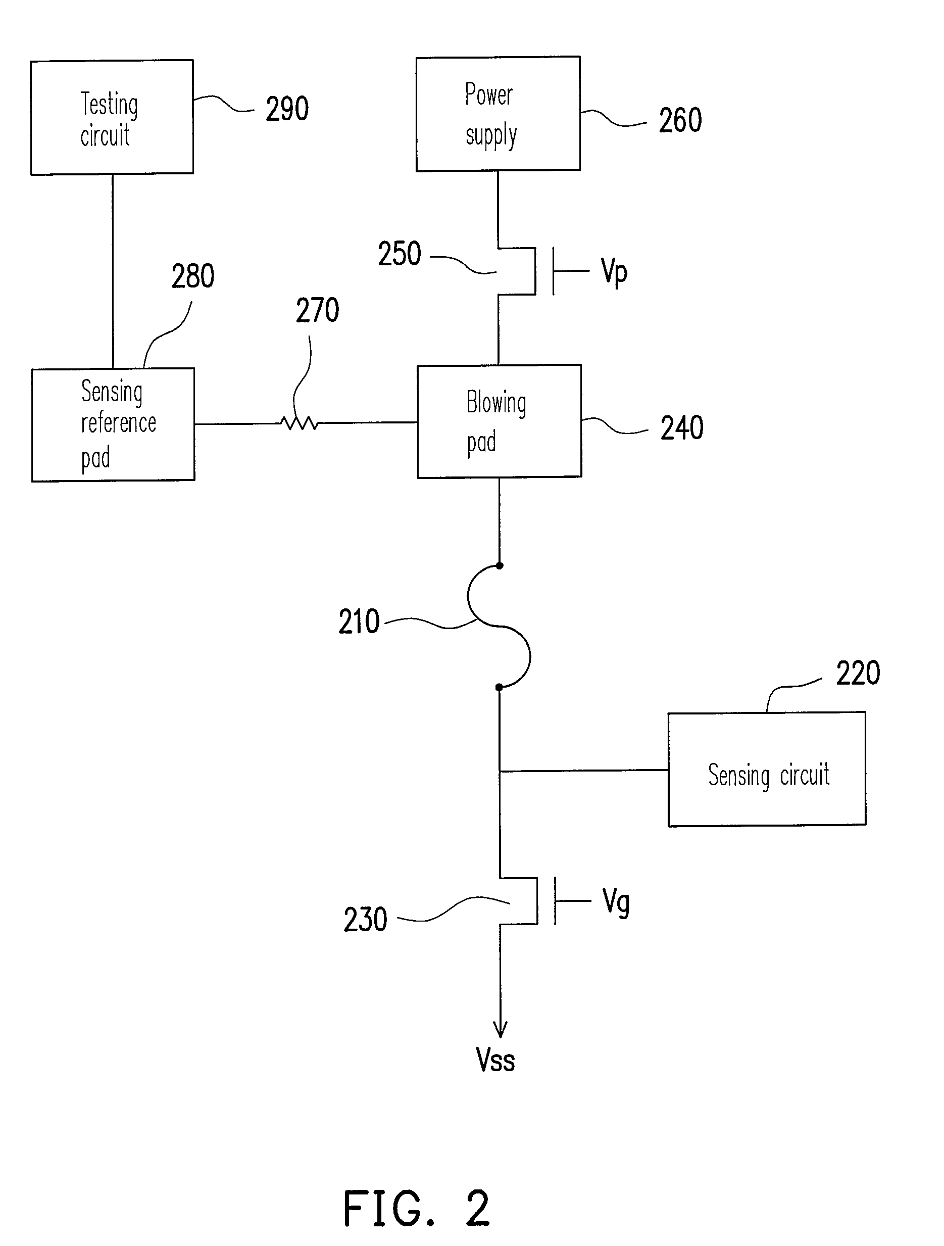
[0034]In general, an eFuse system is programmed at room temperature (25 centigrade, for example) and tested at high temperature (90 centigrade, for example). However, the trigger point resistance of the sensing circuit in the eFuse system is temperature sensitive, such that the trigger point resistance usually increases whenever the eFuse system is tested. In order to eliminate the influence of temperature, the criteria for pass determination has to be raised, in which to dispose an offset resistor to the eFuse system is a way to accomplish the objective. Therefore, the present invention provides an eFuse system and a method for testing the eFuse system according to the foregoing concept. For a bette...


PUM


Abstract

An eFuse system and a method for testing the eFuse system are provided. The eFuse system includes an eFuse, a sensing circuit, and an offset resistor. The sensing circuit has a trigger point resistance and is coupled to a first end of the eFuse for sensing the resistance of the eFuse, wherein the resistance depends on whether the eFuse is blown or not. Accordingly, the sensing circuit outputs a first signal if the sensed resistance is greater than the trigger point resistance and outputs a second signal if the sensed resistance is less than the trigger point resistance. The offset resistor is coupled to a second end of the eFuse for compensating a shift on the trigger point resistance of the sensing circuit due to temperature change.

Description

BACKGROUND OF THE INVENTION[0001]1. Field of the Invention[0002]The present invention generally relates to a sensing circuit and a testing method thereof, in particular, to an eFuse system and a testing method thereof.[0003]2. Description of Related Art[0004]Along with the advance of chipset design, an innovated technique, electric fuse (eFuse), is published by International Business Machines (IBM) Corporation. The eFuse technique combines contemporary algorithms and micro electric fuse technique, such that through the eFuse technique, wafers can dynamically monitor, adjust, and repair themselves when a demand or a failure occurs in the system. Accordingly, using eFuse technique to produce wafers can enhance performance and evade failure due to unexpected demand.[0005]In the eFuse technique, each wafer is disposed with a plurality of micro electronic fuses. To combine the micro electronic fuses with specific software, internal lines in the wafer can be changed automatically, so as t...

Claims


Application Information

Patent Timeline
IPC IPC(8): G01R31/07G01R31/74
CPCG01R31/07G01R31/2853H01L23/5256G11C17/18G11C17/16G01R31/74H01L2924/0002H01L2924/00
Inventor KUO, CHIEN-LI
Owner UNITED MICROELECTRONICS CORP
Why Eureka
Try Eureka