Liquid crystal display device

a liquid crystal display and display device technology, applied in the manufacture of electrode systems, electric discharge tubes/lamps, instruments, etc., can solve the problems of shortening the life of the device, affecting the display quality, and affecting the quality of the display, so as to achieve the effect of high-quality image, variation in the orientation of vapor deposition, and without lowering the contras

Inactive Publication Date: 2009-03-26
CANON KK
View PDF27 Cites 7 Cited by
  • Summary
  • Abstract
  • Description
  • Claims
  • Application Information

AI Technical Summary

Benefits of technology

[0032]In the liquid crystal display device using the inorganic alignment film according to the present invention, by converting an incident light from a light source into a circularly polarized light and irradiating a liquid crystal shutter with the converted light, a high-quality image can be displayed without lowering the contrast even when an optical axis is deviated by a variation in vapor deposition angle. Because the vapor deposition orientation may be varied, it is possible to select a vapor deposition method in which a wide variation in vapor deposition orientation is allowed and a variation in vapor deposition angle can be made small, with the result that a variation in pretilt angle can be suppressed as small as possible. Further, since the chip yield can be increased, the production cost of a liquid crystal shutter can be reduced, thereby providing a low-cost liquid crystal display device.

Problems solved by technology

However, when the conventional liquid crystal shutter is irradiated with such an intense light, there is the problem that the alignment film made of an organic polymer material is degraded to shorten the life thereof.
In general, since the organic alignment film is inferior in light resistance, using the inorganic alignment film in place of the organic alignment film makes it possible to suppress the degradation of the displaying quality resulting from the irradiation with the intense light.
One of problems involved in the oblique vapor deposition is that, because of the vapor deposition from a point-like vapor deposition source, the vapor deposition orientation and the vapor deposition angle differ from each other at respective points on the substrate for deposition, with the result that the growing directions of columns in plane are not uniform and the columns are formed in different orientations and at different angles in respective locations on the substrate.
However, even in this method, the vapor deposition angle and the vapor deposition orientation do not become completely uniform on the substrate.
In particular, when the alignment orientation of the crystal in a substrate plane varies for each chip, the optical axis of the liquid crystal shutter is not fixed.
This critically impairs the contrast of a displayed image.
However, when the characteristics of the respective shutters are different from each other as described above, a displayed color varies for each product, so that constant color reproduction cannot be obtained.
In addition, the displaying quality of each product is not improved.
Therefore, it is difficult to reduce the production cost per chip.

Method used


Image

  • Liquid crystal display device
  • Liquid crystal display device
  • Liquid crystal display device

Examples


example 1

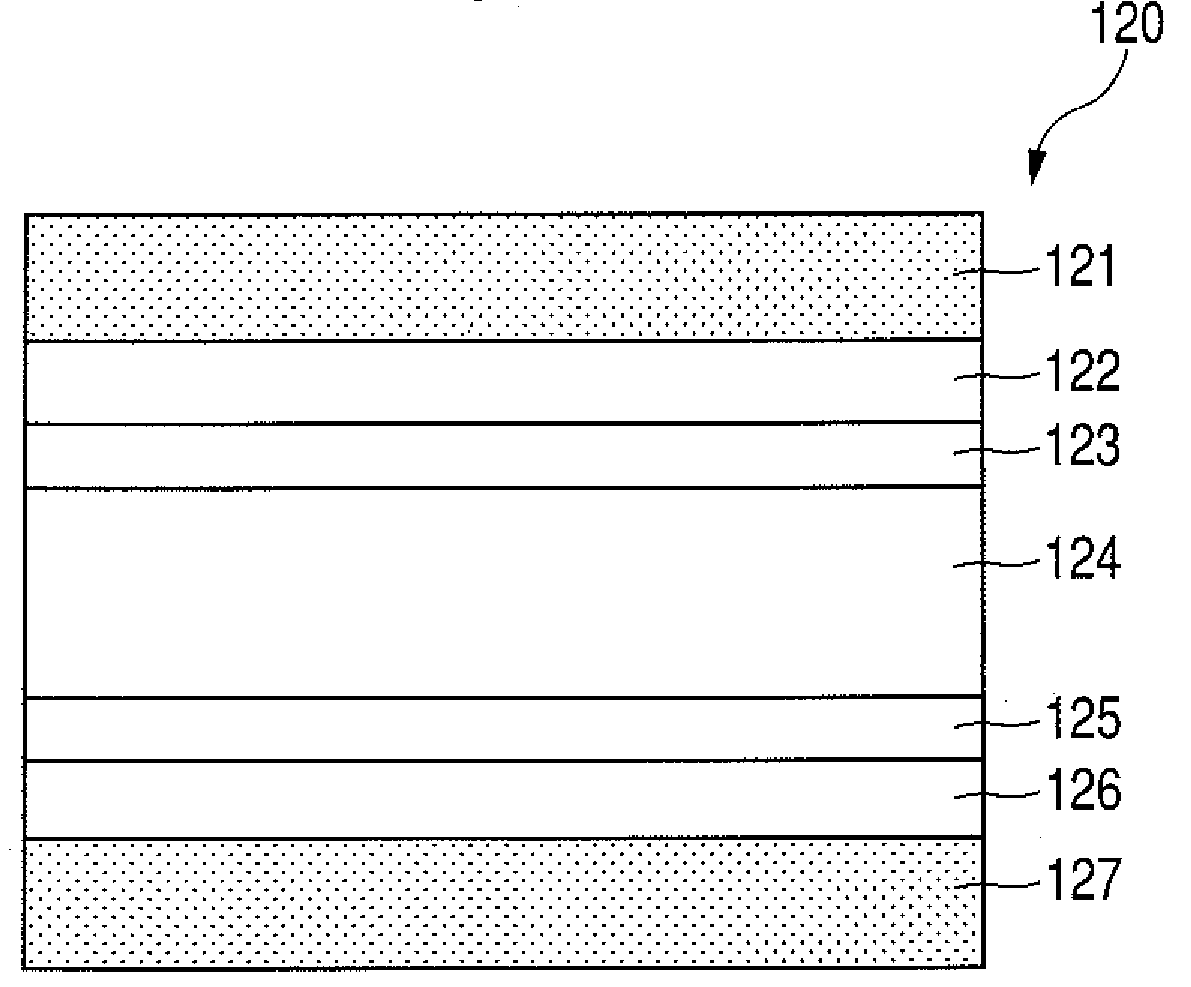
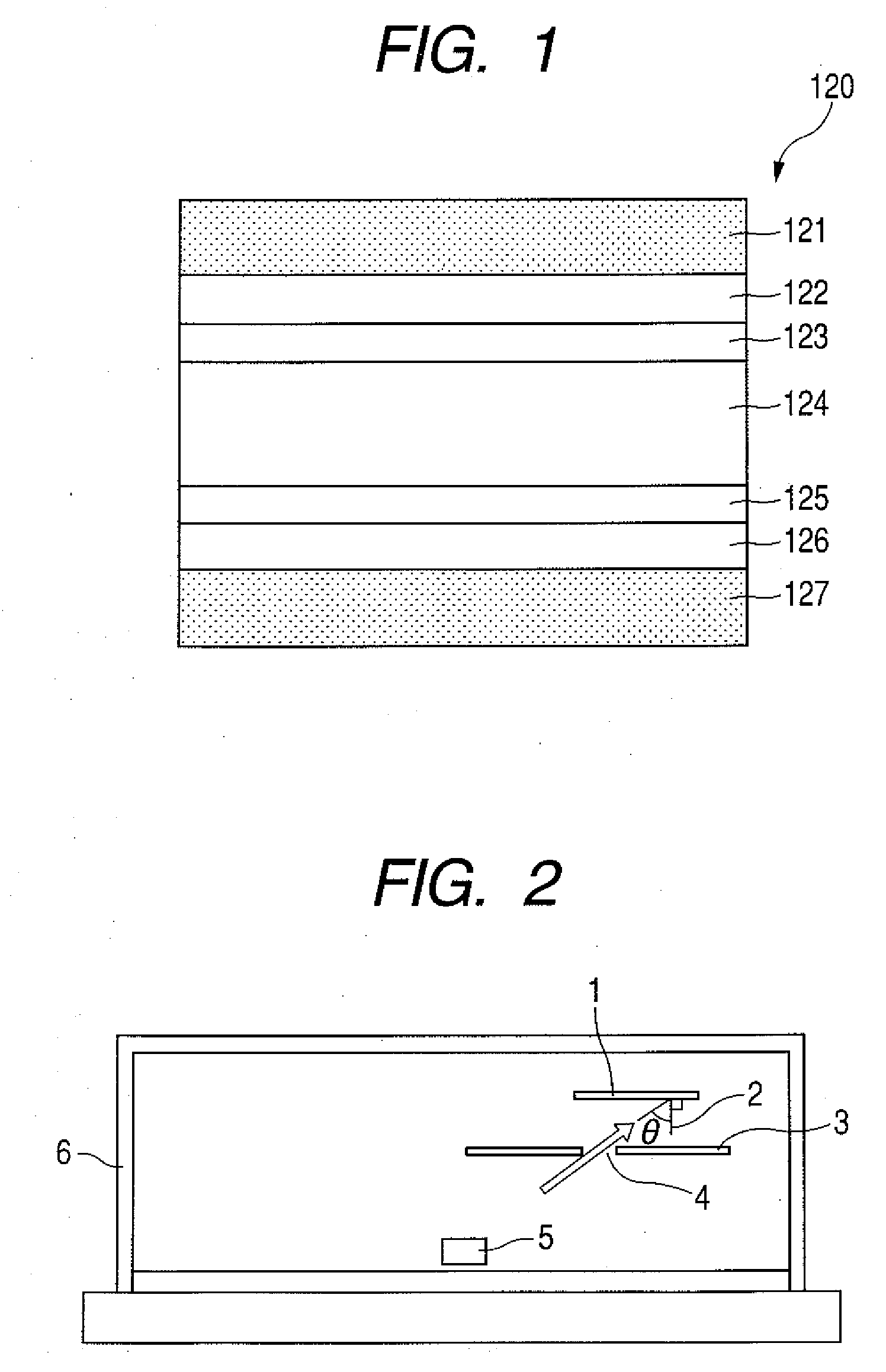
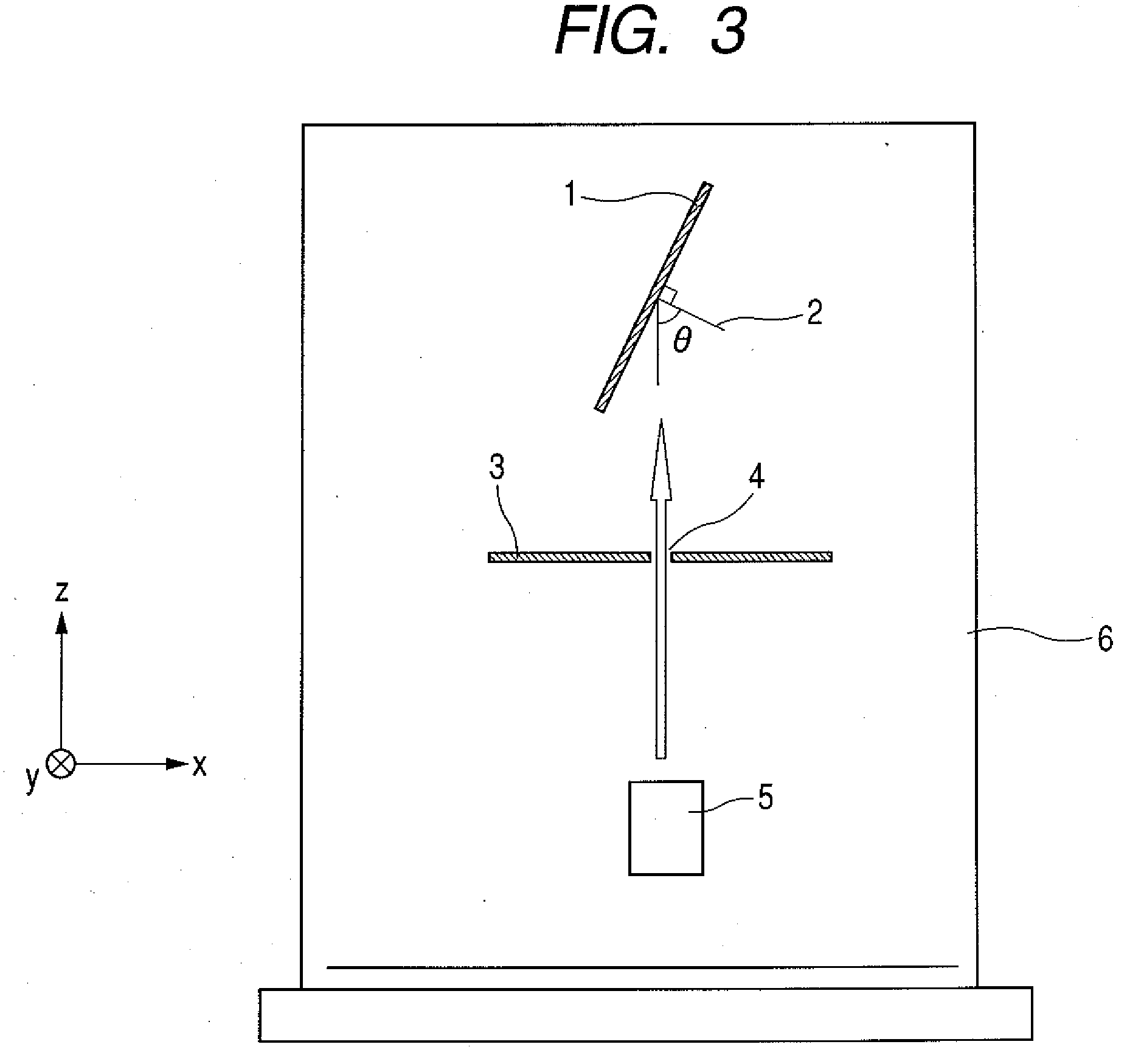
[0101]In this example, the alignment films 123, 125 are formed by the vapor deposition apparatus of the configuration as shown in FIG. 2 to produce a liquid crystal element. At this time, the distance between the vapor deposition source 5 and the substrate 1 is set to 1 meter. The liquid crystal element is used to obtain a projection type liquid crystal display device.

[0102]With respect to an optical system of the projection type liquid crystal display device, two types of optical systems, an optical system for making a linearly polarized light enter the liquid crystal element and an optical system for making a circularly polarized light enter the liquid crystal element, are compared with each other.

[0103]In the case of the projection type liquid crystal display device using the linearly polarized light, a variation in contrast is caused according to the attached liquid crystal element. On the other hand, in the case of the projection type liquid crystal display device using the cir...

example 2

[0104]In this example, an alignment film is formed on one of the substrates by the vapor deposition apparatus shown in FIG. 2 and an alignment film for vertical alignment is formed on the other substrate by using an apparatus of the configuration conceptually shown in FIG. 13 through constant-speed rotary oblique vapor deposition method of rotating the substrate 1 at a constant speed during vapor deposition as indicated by an arrow 8 in FIG. 13. Incidentally, in each film formation, the distance between the vapor deposition source and the corresponding substrate is set to 1 meter. A projection type liquid crystal display device is assembled using the thus produced liquid crystal element.

[0105]A circularly polarized light is used as the polarized light for incidence on the liquid crystal element. As a result, there is obtained an image which has high uniformity and no variation in display due to the liquid crystal element.

example 3

[0106]In this example, an optical system shown in FIG. 14 is used instead of the optical system shown in FIG. 12.

[0107]In FIG. 14, a light emitted from a light source 50 is converted into a linearly polarized light by passing though a linearly polarizing plate 51 and then converted into a circularly polarized light by passing through a quarter-wave plate (λ / 4 plate) 52. Thereby, a liquid crystal element 120 is irradiated with the circularly polarized light.

[0108]In the case of an alignment state in which there is no retardation of the liquid crystal layer, the light is reflected in a state of the circularly polarized light by a reflecting plate (not shown) contained in the liquid crystal element 120. The circularly polarized light passes through the λ / 4 plate 52 again to be converted into a linearly polarized light. At this time, the linearly polarized light becomes to have a polarization state of a polarization direction perpendicular to that of the incident polarized light. After ...


PUM

PropertyMeasurementUnit
pretilt anglesaaaaaaaaaa

Abstract

An inorganic alignment film including an inclined columnar structure is used as an alignment film 123, 125 of a liquid crystal element 120, and a light L1 emitted from a light source 50 for incidence on the liquid crystal element 120 is irradiated to the liquid crystal element 120 through a circularly polarizing means 53. Thereby, variations in optical characteristics which are caused by conventional oblique vapor deposition can be reduced.

Description

TECHNICAL FIELD[0001]The present invention relates to a liquid crystal display device, and more particularly, to a liquid crystal display device using an inorganic alignment film as an alignment film.BACKGROUND ART[0002]At present, liquid crystal display devices have widely been put to practical use. In the future, the liquid crystal display devices are expected to become more and more popular. The liquid crystal display devices can be categorized into a direct view type in which an image having a size equal to that of a liquid crystal element is observed, and a projection type in which an image having a size larger than the size of the liquid crystal element can be observed using a magnifying optical system.[0003]The projection type liquid crystal display device can easily realize large area display and is thus widely used as a front projector for projection from the front of a screen and a rear projector for projection from the rear of a screen.[0004]In the projection type liquid ...

Claims


Application Information

Patent Timeline
Patent Type & Authority Applications(United States)
IPC IPC(8): G02F1/1335H01J9/26
CPCG02F2001/133541G02F1/133734G02F1/133541
Inventor ASAO, YASUFUMI
Owner CANON KK
Why Eureka
Try Eureka