Mixing Machine For Components

a technology of components and mixing machines, applied in the field of components conveying apparatus, can solve the problems of high cost and maintenance costs of such solutions, and achieve the effects of improving the adjustment of components, good mixture, and increasing the possibility of supplying components

Inactive Publication Date: 2009-03-26
VMI AZ EXTRUSION
View PDF6 Cites 16 Cited by
  • Summary
  • Abstract
  • Description
  • Claims
  • Application Information

AI Technical Summary

Benefits of technology

[0021]It is preferred to select the component 1, i.e. the component supplied by the first subsidiary conveyor, in such a manner that this component is the component that is most difficult to mix. This ensures that over the progression of the extruder an especially good mixture can be achieved. Accordingly, the component n−1 is supplied considerably more far downstream, whereby it is preferred to use the component n−1 as the component that is intermingles most easily.
[0022]By the use of multiple-screw extruders, the possibilities for supplying the components can be considerably increased and a still better adjustment to the components to be mixed can be realized.
[0023]The invention is also well-suited for the use of thermoplastic elastomers. A relatively long extruder screw can be employed for the cross-linking or polymerization process. The rubber component can be prepared separately, with reference to the total mixture in a ratio of 20 to 40% for example, whereby filling material can be supplied via the subsidiary conveyors for example. The subdivision elastomer / thermoplastic by means of two separate extruder screws also offers the advantage that material damages relative to one another can be avoided to a large extent such that also peroxides can be employed instead of phenolic resin, resulting in improved cross-linking.

Problems solved by technology

Solutions of this kind are often expensive and maintenance-extensive to this extent since each subsidiary conveyor must be maintained separately.

Method used


Image

  • Mixing Machine For Components
  • Mixing Machine For Components

Examples


Embodiment Construction

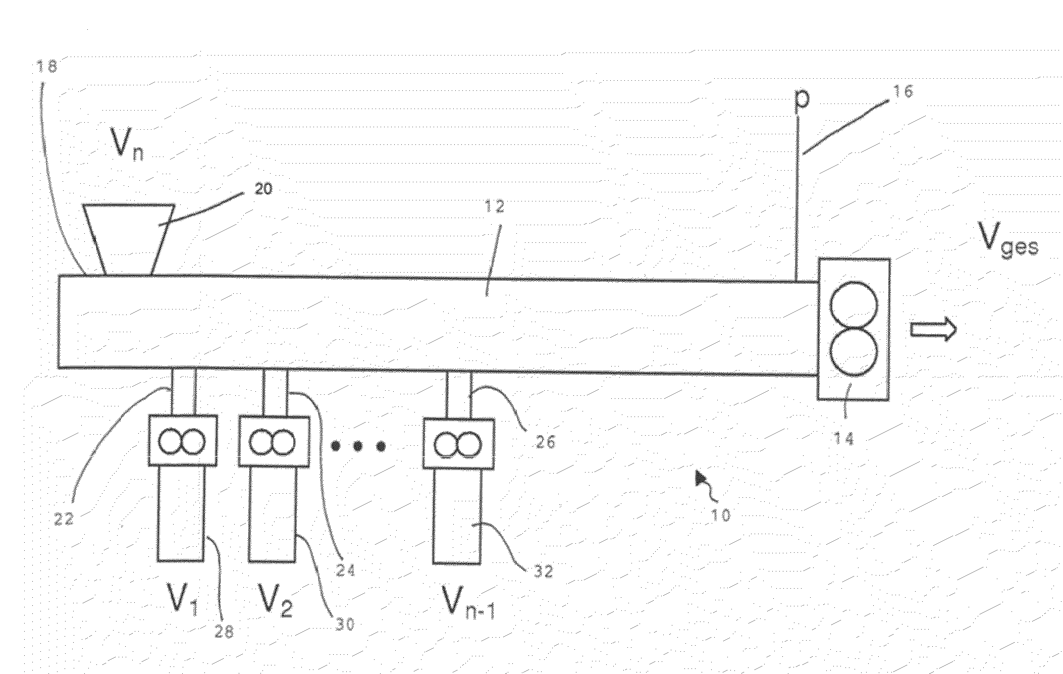
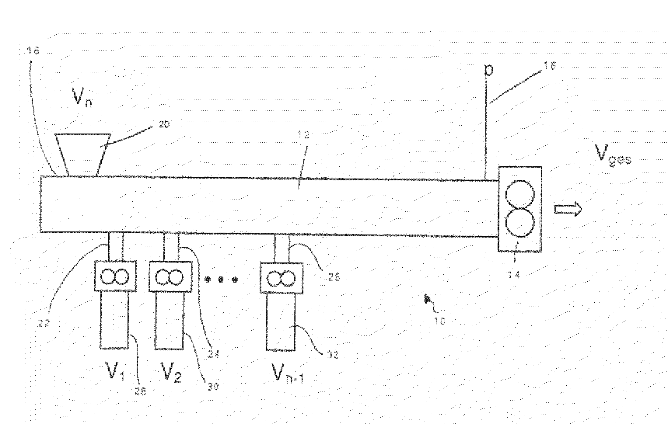
[0028]The extrusion conveying apparatus 10 shown in the figure includes an extruder 12 constituting the central element of the extrusion conveying apparatus. The extruder is intended for the extrusion and conveying of extrudable mixtures including rubber mixtures and thermoplastic elastomers (TPEs) for example. The extruder is intended for delivering a volume flow that is designated with Vges in this case. A volumetric conveyor 14 that is embodied as a gear pump, is provided on the output side of the extruder 12. The drive mechanism of the gear pump 14 is independent of the drive mechanism of the extruder 12.

[0029]Further, a pressure sensor 16 that measures the pressure existing at that position and that adjusts the drive speed of the extruder 12 correspondingly is provided on the output side of the extruder 12.

[0030]Various feeding positions or locations are provided laterally on the extruder 12. At a first feeding position 18 a feeding apparatus 20 is mounted by means of which par...


PUM

PropertyMeasurementUnit
pressureaaaaaaaaaa
pressureaaaaaaaaaa
pressureaaaaaaaaaa

Abstract

An extrusion conveying apparatus, including an extruder that operates as a mixing device and is laterally supplied with components that are to be mixed, in particular components of a rubber mixture or thermoplastic elastomer. A volumetrically operating conveyor, in particular a gear pump, is connected to the output side of the extruder. A rotational speed or feed rate of the extruder is adjustable independently of the feed rate and volume flow of the conveyor. n−1 volumetric subsidiary conveyors are provided for passage of components therethrough where there are n components of a mixture. In particular component n is supplied in an undosed manner. A rotational speed or feed rate of the subsidiary conveyors is adjustable independently of the feed rate of the volumetrically operating conveyor.

Description

[0001]The instant application should be granted the priority date Sep. 24, 2007 the filing date of the corresponding German patent application DE 10 2007 045 533.1.BACKGROUND OF THE INVENTION [0002]The invention relates to an extrusion conveying apparatus having an extruder that operates as a mixing device and that can be laterally supplied with components that are to be mixed, in particular components of a rubber mixture or thermoplastic elastomer (TPE), whereby a volumetrically acting conveyor, in particular a gear pump, is connected to an output side of the extruder, and whereby the components that are supplied pass through volumetric subsidiary conveyors, which in particular are also embodied as gear pumps and the rotation speed or feed rate of which is adjustable independently of the feed rate of the volumetrically acting conveyor.[0003]Conveying apparatuses of this kind are employed in order to produce a mixture to be extruded from a plurality of components. It is known that t...

Claims


Application Information

Patent Timeline
Patent Type & Authority Applications(United States)
IPC IPC(8): B29C47/10B29C48/03B29C48/285B29C48/37B29C48/38B29C48/39B29C48/395B29C48/56B29C48/92
CPCB29C47/0009B29C47/364B29C47/1081B29C47/367B29C47/369B29C47/38B29C47/6043B29C47/666B29C47/82B29C47/825B29C47/92B29C2947/92019B29C2947/92104B29C2947/9218B29C2947/92314B29C2947/9238B29C2947/92514B29C2947/9259B29C2947/926B29C2947/92704B29C2947/92714B29C2947/92809B29C2947/92866B29C2947/92876B29C2947/92885B29K2021/00B29C47/10B29C48/83B29C48/92B29C2948/92704B29C2948/92876B29C48/297B29C48/03B29C48/285B29C48/37B29C48/387B29C48/39B29C48/395B29C48/56B29C48/686B29C48/834B29C2948/92019B29C2948/92104B29C2948/9218B29C2948/92314B29C2948/9238B29C2948/92514B29C2948/9259B29C2948/926B29C2948/92714B29C2948/92809B29C2948/92866B29C2948/92885B29B7/603B29B7/38B29B7/726B29B7/728B29B7/7495
Inventor SKIBBA, OLAF
Owner VMI AZ EXTRUSION
Why Eureka
Try Eureka