
Gas supply system of natural gas single-fuel engine

A gas supply system and engine technology, applied to combustion engines, internal combustion piston engines, charging systems, etc., can solve problems such as automatic adjustment of the mixture, failure to ensure the mixture of the mixture, and the engine's inability to mix gas and air.

Inactive Publication Date: 2012-01-11
GEELY SICHUAN COMML VEHICLE CO LTD
View PDF1 Cites 0 Cited by
  • Summary
  • Abstract
  • Description
  • Claims
  • Application Information

AI Technical Summary

Problems solved by technology

The above-mentioned patents provide a wide variety of gas mixers. The general trend is that all internal combustion engines that utilize natural gas as fuel have an air supply system that supplies air and gas to the engine. The air passes through an air filter, Enter the exhaust gas turbocharger, after pressurization, it enters the intercooler from the air outlet, and the intercooled air enters the mixer. The gas is compressed natural gas, and the high-pressure natural gas stored in the cylinder is decompressed by the first-stage pressure reducer. Connected to the stop valve, to the second-stage pressure reducer, to the third-stage pressure reducer..., the last stage forms the final stage pressure reducer, and the gas outlet of the final stage pressure reducer is connected to one of the gas mixers. The gas ends are connected, and the two gases are fully mixed in the mixer and then supplied to the combustion chamber of the engine cylinder, but such a system cannot automatically adjust the required mixed gas according to the needs of the engine working conditions. To solve this problem, people have designed the Ecu system to automatically adjust the gas entering the cylinder, but such a system cannot guarantee that the mixed gas is mixed at the best ratio, and the engine cannot obtain the best gas-air mixing ratio at all times, thereby obtaining the maximum output. The mixer structure must solve how to mix the two gases evenly, but it does not pay attention to the pressure changes of the gas and air involved in the mixing. The pressure is related to the flow rate, especially the pressure difference between the two gases. Therefore, the current system is flawed

Method used


Image

  • Gas supply system of natural gas single-fuel engine
  • Gas supply system of natural gas single-fuel engine
  • Gas supply system of natural gas single-fuel engine

Examples


Embodiment Construction

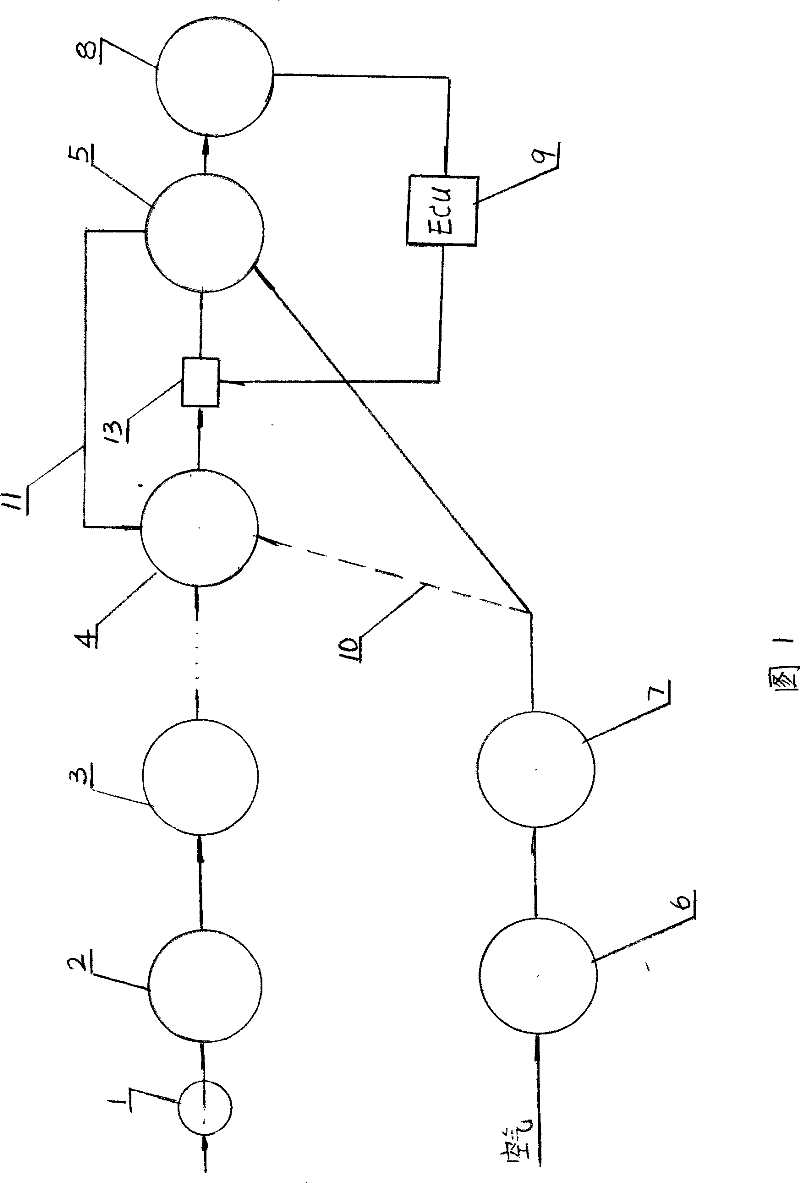
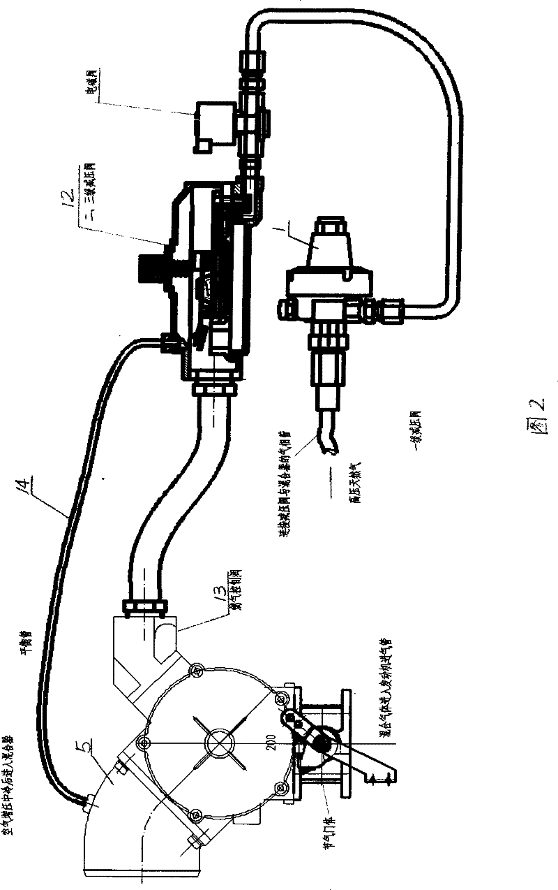
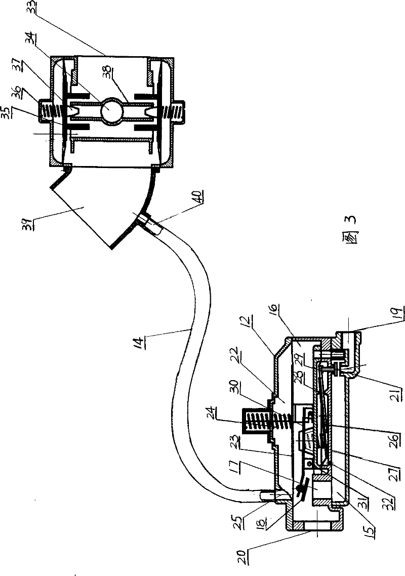
[0011] Such as figure 1 In the system block diagram shown, the high-pressure natural gas in the steel cylinder enters the high-pressure reducer 1 through the pipeline → the second-stage reducer 2 → the third-stage reducer 3 ... the final-stage reducer 4, and the final-stage reducer 4 enters the mixer There is an air supply valve 13 directly between the 5, and the other branch enters the exhaust gas supercharging turbine 6 from the air → cools through the intercooler 7 → enters the mixer 5, and the gas outlet of the mixer 5 enters the engine cylinder 8, and the system is connected with Two branches, one belongs to the ECu control system of known technology, ECu is indicated by subscript 9, and the other branch is designed for the solution of the present invention, which can be directly connected to the final stage pressure reducer through the branch 10 from the intercooler 4. Use a dotted line to indicate that this is a conceivable connection. The specific connection is from th...


PUM


Abstract

The invention discloses a gas supply system of a natural gas single-fuel engine. The gas supply system supplies air and fuel gas to an engine, the air passes through an air filter and enters a waste gas turbo pressurizer; the air enters an intercooler from an air outlet after being pressurized; the intercooled air enters a mixer; the fuel gas is a compressed natural gas; a high-pressure natural gas stored in a steel bottle is decompressed by a first class decompressor and connected to a stop valve, a second class decompressor, a third class decompressor till the last class decompressor by a pipeline to form a final class decompressor; the air outlet end of the last class decompressor is communicated with the air inlet end of the air mixer; two gases are supplied to a combustion chamber ofan engine cylinder after being fully mixed in the mixer; and the intercooled air pressurized by a turbo mainly enters the mixer (5) and is also communicated with the last class decompressor of the fuel gas by a balance tube (14). The system can automatically adjust the differential pressure between the mixed fuel gas and the air and ensure the differential pressure to be in a constant value range, thereby mixing the fuel gas and the air in a best proportion.

Description

technical field [0001] This invention relates generally to an internal combustion engine, and more particularly to an engine that uses natural gas as fuel. Background technique [0002] As the price of fuel oil such as gasoline and diesel used in internal combustion engines continues to rise, people turn to research on natural gas engines in order to better utilize my country's natural gas resources. For example, our company once applied for a Chinese invention patent named "Natural Gas Single Fuel Supercharged engine", the patent application number is 2005100223208, which discloses a gas mixing device, which uses the mixing device to supply gas to the engine to replace the traditional EFI gas supply method. Those with mixer devices are not only patents applied by our company, such as Chinese invention patent, titled "engine natural gas mixer", application number 200510018722.0, the applicant is Dongfeng Motor Co., Ltd.; Chinese utility model patent application, titled "natura...

Claims


Application Information

Patent Timeline
Patent Type & Authority Patents(China)
IPC IPC(8): F02M21/04
CPCY02T10/32Y02T10/30
Inventor 万义军杨志勇张自力程辉刘延伟陈孟强
Owner GEELY SICHUAN COMML VEHICLE CO LTD
Learn More