
Light-emitting diode, lighting device and method of manufacturing same

a technology of light-emitting diodes and lighting devices, which is applied in the direction of discharge tubes/lamp details, discharge tubes luminescnet screens, electric discharge lamps, etc., can solve the problems of undesirable color deviation, complex process, and the thickness of the phosphor layer must be very accurately controlled, so as to achieve accurate control

Inactive Publication Date: 2009-05-19
LUMILEDS
View PDF13 Cites 1 Cited by
  • Summary
  • Abstract
  • Description
  • Claims
  • Application Information

AI Technical Summary

Benefits of technology

[0008]To achieve this, in accordance with the invention, the light-emitting surface comprises a sub-surface without the phosphor layer. From the sub-surface without the phosphor layer issues light (preferably blue light) of the first wavelength (for example approximately 480 nm), which corresponds to the light emitted by the chip (preferably an InGaN chip), and from the sub-surface with the phosphor layer issues the converted light (preferably yellow light) of the second wavelength (for example approximately 575 nm). If both colors mix, light of a different color is obtained. Consequently, the color temperature can be accurately controlled by the choice of the size of the sub-surface. In a preferred embodiment, the size of the sub-surface is such that mixing the emitted light of the first and the second wavelength results in substantially white light. If necessary, a third sub-surface can be covered with a layer of a second type of phosphor which emits light of a third wavelength. In this manner, any desired color can be accurately obtained.
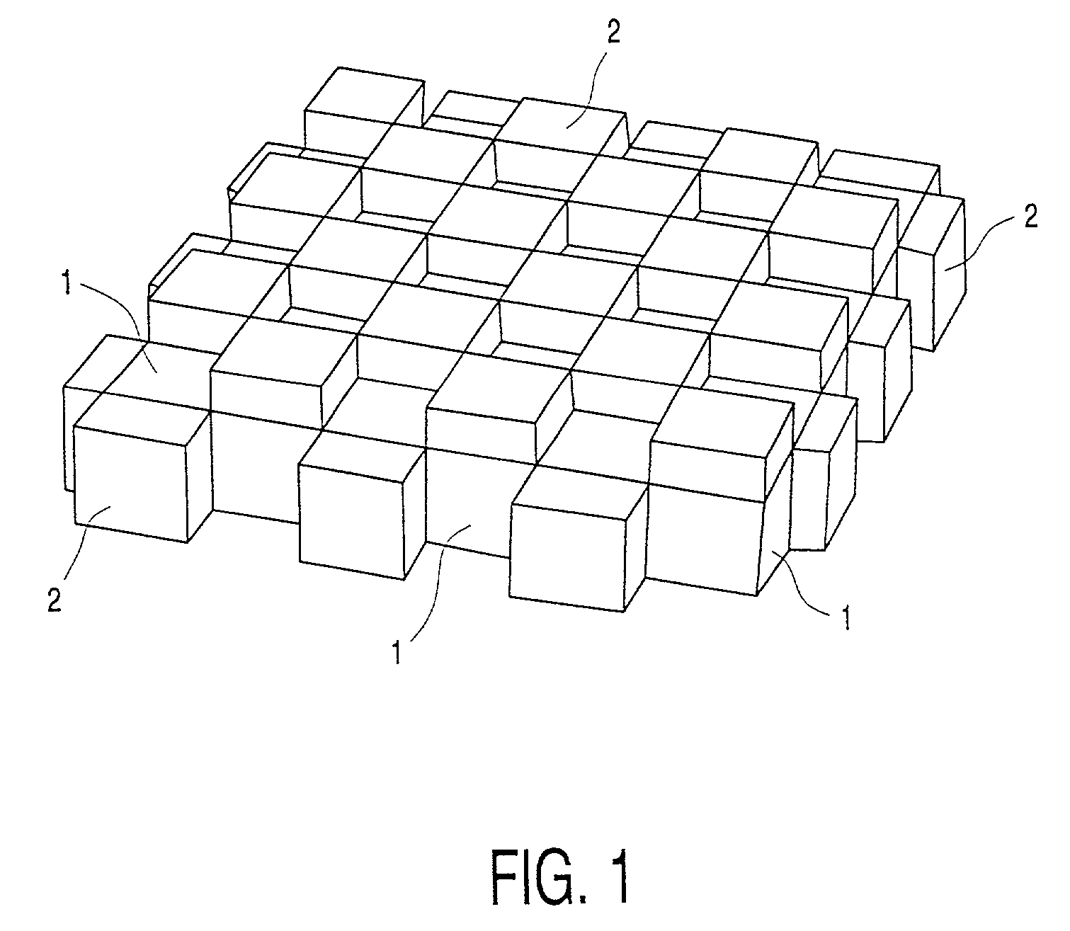
[0011]Preferably, the sub-surface without a phosphor layer, or the sub-surface on which the phosphor layer is provided, is distributed over a plurality of partial sub-surfaces, said partial sub-surfaces preferably forming a pattern, such as a simple chessboard pattern. This pattern is preferably very finely distributed, so that a good mixture of the light is obtained. In certain applications, too coarse a pattern may cause the color pattern to be undesirably projected on the object to be illuminated. To further reduce this effect, a lighting unit wherein a light-emitting diode in accordance with the invention is incorporated preferably comprises optical elements to mix the emitted light of the first and the second wavelength.

Problems solved by technology

The above-described LED has the disadvantage that in order to obtain a light output having a predetermined, accurate color temperature, the thickness of the phosphor layer must be very accurately controlled, which is a complex process.
As a result, in practice, variations in the thickness of this layer occur, which may lead to undesirable color deviations, which may range from several thousand to several hundred Kelvin in color temperature.
A drawback of this diode resides in that a large quantity of the phosphor mass must be cast around the chip because all the (ultraviolet) light emitted by the chip must be converted to visible light.

Method used


Image

  • Light-emitting diode, lighting device and method of manufacturing same
  • Light-emitting diode, lighting device and method of manufacturing same
  • Light-emitting diode, lighting device and method of manufacturing same

Examples


Embodiment Construction

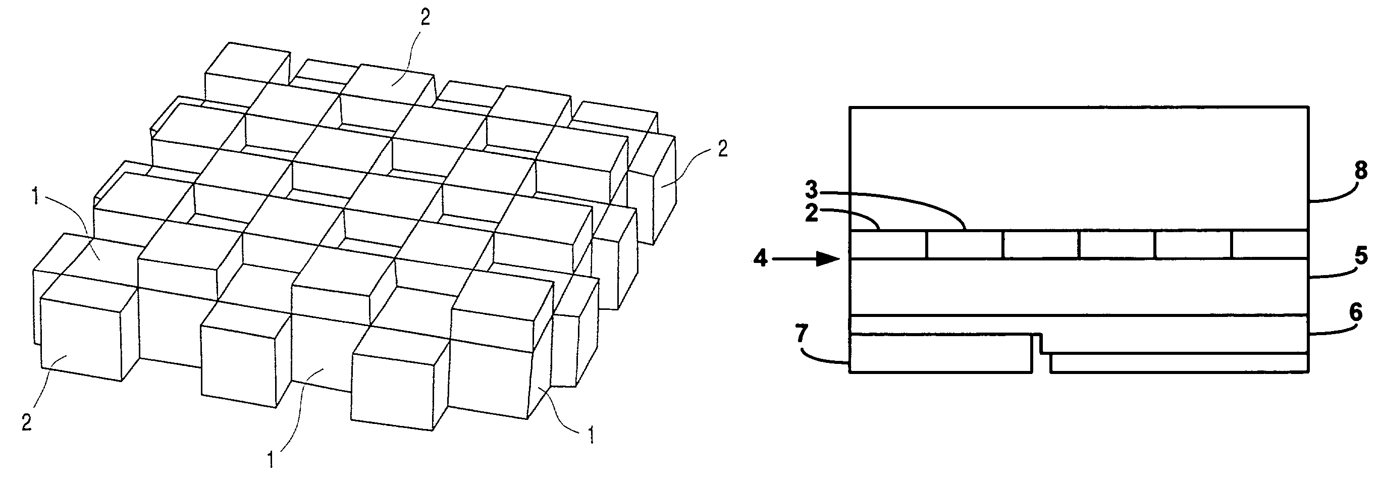
[0020]As shown in FIG. 1, a light-emitting diode comprises an InGaN chip 1 having a light-emitting chip surface. On the lower side of the chip there are electric connectors. A phosphor layer is applied to the chip surface by means of screen printing. In this example, said layer is formed by small phosphor blocks 2, which are arranged in accordance with a chessboard pattern. The surface of the chip covered with the phosphor blocks 2 forms the covered sub-surface of the chip, the surface covered by an individual block 2 being referred to as a partial sub-surface. The phosphor layer may be, for example, a TG:Eu phosphor.

[0021]If an electric voltage is applied to the InGaN chip, then this chip emits blue light of a wavelength of approximately 480 nm. Subsequently, the blue light issues freely to the exterior through the uncovered sub-surface. The blue light incident on the sub-surface covered with the phosphor blocks 2, however, is absorbed by the phosphor blocks and converted to yellow...


PUM


Abstract

A light-emitting diode comprises a chip emitting visible light of a first wavelength, a light-emitting surface and a phosphor layer provided on the light-emitting surface. Said phosphor layer is capable of converting light of the first wavelength to visible light of a second wavelength. According to the invention, a part of the light-emitting surface is not covered with the phosphor layer. Preferably, the size of said surface is chosen to be such that by mixing emitted light of the first and the second wavelength substantially white light is obtained. Preferably, the surface that is not covered with the phosphor layer comprises a plurality of sub-surfaces, preferably arranged in the form of a pattern.

Description

BACKGROUND[0001]1. Field of Invention[0002]The invention relates to a light-emitting diode comprising a chip capable of emitting visible light of a first wavelength, a light-emitting surface and a phosphor layer which is provided on the light-emitting surface and which is capable of converting light of the first wavelength to visible light of a second wavelength.[0003]2. Description of Related Art[0004]Such a light-emitting diode (LED) is well known. In the case of an LED, the chip emits colored light of one specific wavelength. Hitherto, LEDs were predominantly used as signal lamps, but as a result of the increased light output, LEDs are increasingly used, at present, to illuminate objects. In many applications there is a trend towards illuminating an object with light of a different color, particularly light comprising different wavelengths, for example substantially white light, which is the reason why the light-emitting surface of the known LED is provided with a phosphor layer ...

Claims


Application Information

Patent Timeline
Patent Type & Authority Patents(United States)
IPC IPC(8): H01J1/62H01L33/50
CPCH01L33/508
Inventor KEUPER, MATTHIJS HENDRIK
Owner LUMILEDS
Learn More