Computer Controllable LED Light Source for Device for Inspecting Microscopic Objects

a led light source and microscopic technology, applied in the direction of fluorescence/phosphorescence, material analysis using wave/particle radiation, instruments, etc., can solve the problems of difficult to grow successful crystals, limited x-ray crystallography, and high cos

Inactive Publication Date: 2009-03-26
RIGAKU AUTOMATION
View PDF21 Cites 27 Cited by
  • Summary
  • Abstract
  • Description
  • Claims
  • Application Information

AI Technical Summary

Problems solved by technology

However, despite its promises, X-ray crystallography is limited by the fact that it is very difficult to grow successful crystals.
Crystals however, grown by this method are often larger and of higher quality.
Regardless of the method chosen, protein crystal growth is a very delicate and time-consuming process.
The above system is riddled with opportunities for human error.
The operator may be subject to physical fatigue, suffer eyestrain, and may be uncomfortably cold in the temperature controlled and generally high humidity room.
The operator can be tired and confused and can easily make errors in manually recording data in the notebook.
Additional transcription errors may occur when the data is transferred to a computer database.
One of the problems with these prior art techniques is that salt crystals may also form in the hanging or sitting drops and these salt crystals typically cannot be distinguished from protein crystals with the visible light cameras.
Therefore either very precise filtering is required and even with careful filtering there is a risk of over heating the target drop by the ultraviolet light.
Often the crystals are difficult to precisely locate with the visible light.

Method used


Image

  • Computer Controllable LED Light Source for Device for Inspecting Microscopic Objects
  • Computer Controllable LED Light Source for Device for Inspecting Microscopic Objects
  • Computer Controllable LED Light Source for Device for Inspecting Microscopic Objects

Examples


second preferred embodiment

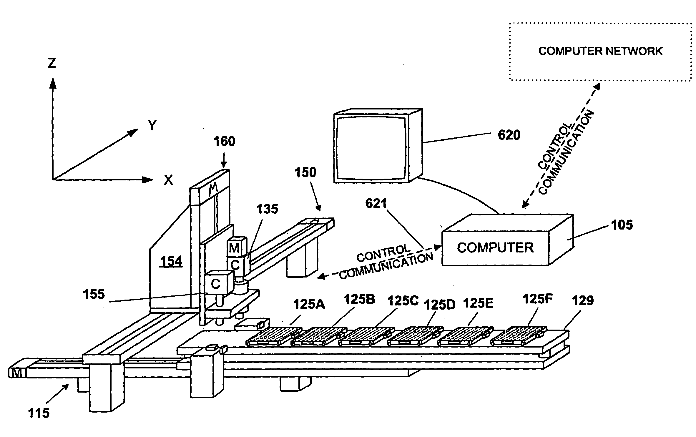
[0103]In a second preferred embodiment, the depth of view of camera 135 is approximately 50 to 100 micrometers. The crystal in the drop of liquid may be larger than the depth of view or there may be crystals growing at various levels within the hanging drop of liquid, as shown in FIG. 29. Therefore, in the second preferred embodiment, lens 145 is focused at multiple different levels 721-724 and a set of images are recorded at the different levels so that the entire crystal may be analyzed.

Specimen Auto-Focus

[0104]The third preferred embodiment of the present invention utilizes a specimen auto-focus subroutine 300 (FIG. 31). Subroutine 300 ensures that the specimen within the micro-well is in-focus at the desired zoom (or magnification ratio) of image lens 145. Utilizing the auto-focus feature, the present invention causes camera 135 to take a number of images defined by a Number_of_Z_Slices. Typically, there are between 5 and 10 slices separated in the Z-axis from one another by a Z...

fourth preferred embodiment

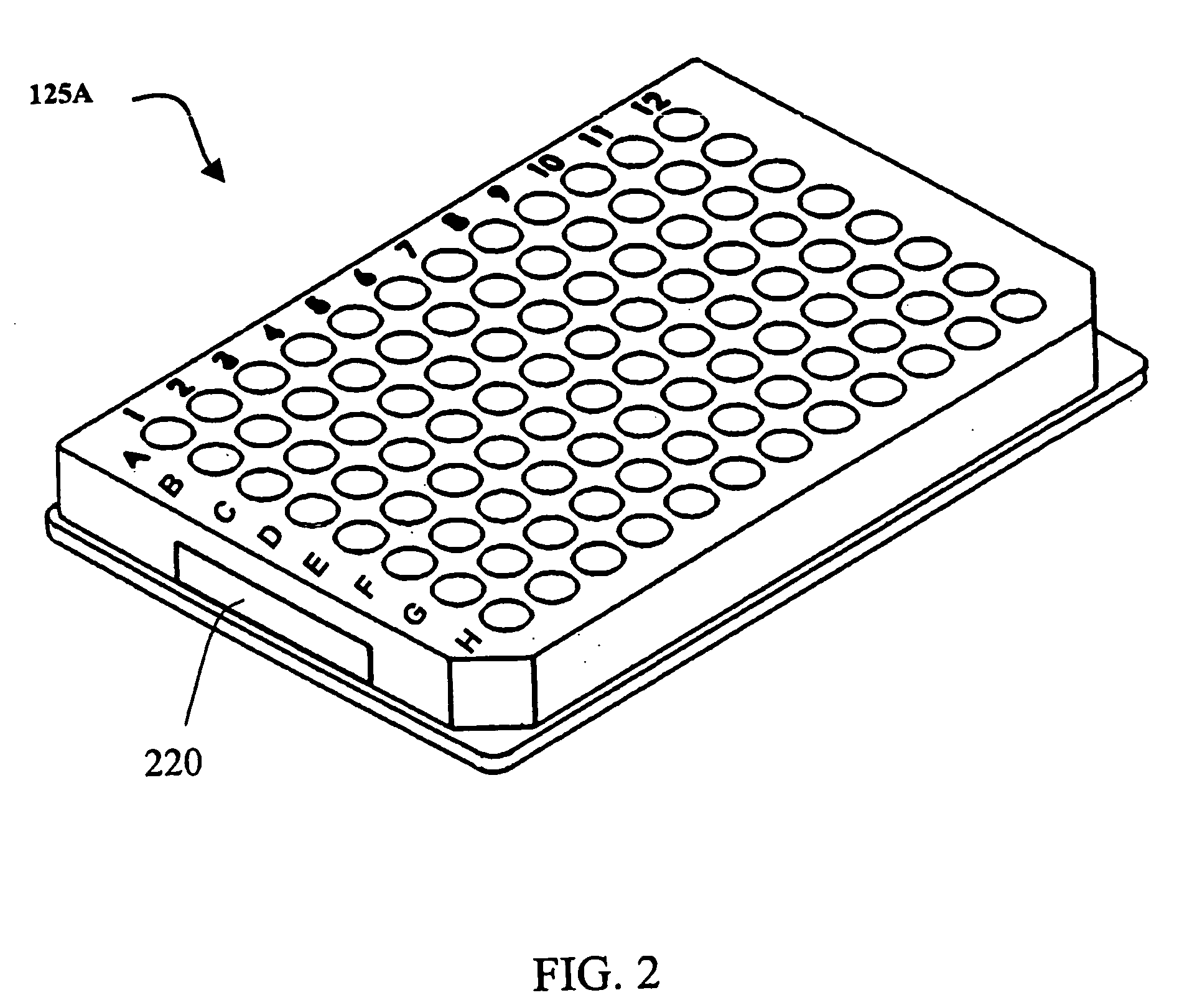
[0106]In the first preferred embodiment, it was disclosed how an operator could manually score each drop of liquid as either “CRYSTAL” or “NO CRYSTAL”. In the fourth preferred embodiment, the operator is given a greater variety of options in deciding on how to score each drop. Table 1 shows listing of the operator's scoring options, including number, text description, and the corresponding color code. Once a micro-well drop has been scored a 9, the operator can further classify the crystals in a scoring shown in Table 2.

TABLE 1SCOREDESCRIPTIONDISPLAY COLOR0clearWhite1light precipitationRed2heavy precipitationYellow3ugly precipitationBlue4phase separationOrange5unknownViolet6SpherolitesBlack7Grainy precipitationGray8MicrocrystalsBrown9CrystalGreen

TABLE 2SCOREDESCRIPTION9.0crystal (no comments)9.1needles, intergrown9.2needles, single9.3plates, intergrown9.4plates, single9.5chunks, 9.6chunks, 9.7chunks, >50 microns, intergrown9.8chunks, >50 microns, single9.9gorgeous >50 microns

fifth preferred embodiment

[0107]In the fourth preferred embodiment, it was disclosed how an operator can manually score each drop of liquid into one of 10 categories with corresponding color coding, and how the operator can score category 9 into further subcategories of 9.0 through 9.9. In the fifth preferred embodiment, the inspection device automatically scores and classifies each drop specimen by executing computer software subroutines as shown in FIGS. 33, 34a, 34b, 34c, 34d, and 35a and 35b under control of the program flow shown in FIG. 36. The automatic classification can occur at three levels of detail, the first level, Type_of_Classification=1, simply discriminates between a drop that is clear or not-clear (unknown), the second level, Type_of_Classification=2, scores and classifies the drop into classes 0 through 9 as described in Table 1 above, and the third level, Type_of_Classification=3, performs second level scoring and classification, plus adds an additional 10 subcategories to the CLASS 9, cr...


PUM

PropertyMeasurementUnit
thickaaaaaaaaaa
thickaaaaaaaaaa
wavelengthsaaaaaaaaaa

Abstract

A device for inspecting microscopic objects. A plurality of LEDS is arranged in an array underneath a lens. Some of the LEDS are lighted and some of the LEDS are unlighted. A computer is in control of the LED array. The computer turns on selected LEDS from the array to form the lighted LEDS. Also, the computer turns off selected LEDS from the array to form the unlighted LEDS. The lighted LEDS form a pattern of lighted LEDS underneath the lens. In a preferred embodiment, the lens is connected to a computer controlled camera and the microscopic objects are microscopic crystals. In another preferred embodiment UV LEDS are utilized and illuminate crystals from above. In another preferred embodiment UV LEDS are utilized to illuminate a loop of a Hampton pin to locate a crystal in the loop of a Hampton pin for the purpose of x-ray crystallography.

Description

[0001]The present invention relates to automated inspection devices, and in particular to automated inspection devices having computer controllable light sources. This application claims the benefit of U.S. provisional application Ser. No. 60 / 961,722, filed Jul. 23, 2007; and U.S. provisional application Ser. No. 60 / 997,839 filed Oct. 5, 2007; and is a continuation in part application of U.S. patent application Ser. No. 10 / 627,386 filed Jul. 25, 2003 (soon to issue as U.S. Pat. No. 7,406,189 on Jul. 29, 2008); which is a continuation in part application of U.S. Pat. No. 6,985,616 which issued on Jan. 10, 2006, all of which are incorporated by reference herein.BACKGROUND OF THE INVENTION[0002]The determination of the three dimensional atomic structure of matter is one of the most important areas of pure and applied research. One way in which the three dimensional atomic structure of matter can be determined is through X-ray crystallography. X-ray crystallography utilizes the diffract...

Claims


Application Information

Patent Timeline
Patent Type & Authority Applications(United States)
IPC IPC(8): G01N23/207G01N21/64
CPCB01J2219/00315B01J2219/00322B01J2219/00328B01J2219/00707B01J2219/00725B01J2219/00756G01N35/028B01L9/523B01L2300/0829G01N21/255G01N21/6458G01N21/6486B01L3/06
Inventor GANZ, BRIAN L.BORKENHAGEN, JAMESROSSMAN, CHRISCOSAND, ANDREWWILLIS, MICHEALCRANE, KEITH
Owner RIGAKU AUTOMATION
Why Eureka
Try Eureka