Bearing having thermal compensating capability

a technology of bearings and components, applied in the field of bearings, can solve the problems of increasing the friction in the internal components, not being able to maintain the bearing settings generally constant over a wide range of temperature, and carrying extremely heavy loads in these applications, so as to achieve less effort, less complex assembly, and low cost

Inactive Publication Date: 2009-03-26
THE TIMKEN CO
View PDF24 Cites 28 Cited by
  • Summary
  • Abstract
  • Description
  • Claims
  • Application Information

AI Technical Summary

Benefits of technology

[0009]The bearing of present invention is a tapered roller bearing that requires little if any machining of the bearing cup. Instead, the thermal compensation components can be positioned against a back face and / or a front face of the bearing in the manner of an add-on accessory to the bearing. This results in a lower cost bearing that is less complex to assemble and which allows for the possibility of adding thermal compensating components to existing bearings or incorporating thermal compensating components to a bearing with less effort.

Problems solved by technology

The tapered roller bearings in these applications carry extremely heavy loads for their size.
While the expansion and contraction of the tapered roller bearings, due to the geometry of the bearings, tends to offset some of the effects of the differential expansion and contraction between the case and shafts, it is not enough to maintain bearing settings generally constant over a wide range of temperature.
Excessive preload into the bearings at assembly can compensate for some of the looseness caused by the case expansion, however, this increases the amount of friction in the internal components and subsequently increases the amount of wear on the internal components.
Additionally, the effort to rotate gears on the shafts will increase during cold start up of the transmission.
On the other hand, when the transmission is heated, excessive end play decreases the size of the zones through which loads are transmitted in the bearings, resulting in spaces and gaps between the components of the bearings, thereby reducing the life of the bearings.
However, the rabbet design of the bearing in that patent requires the bearing cup to be specially machined thereby adding increased cost to the bearing and increases the difficulty of assembling the bearing.

Method used


Image

  • Bearing having thermal compensating capability
  • Bearing having thermal compensating capability
  • Bearing having thermal compensating capability

Examples


Embodiment Construction

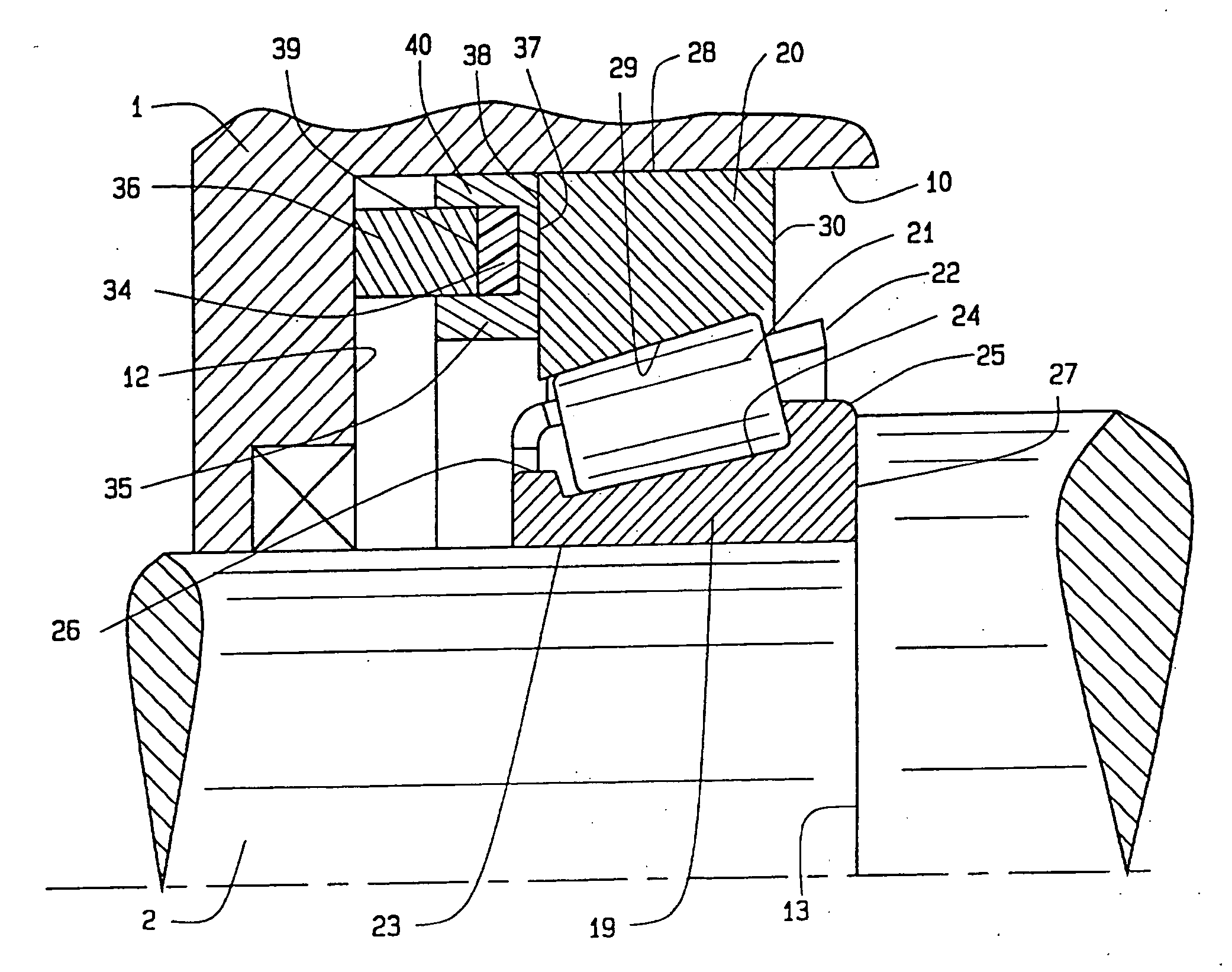
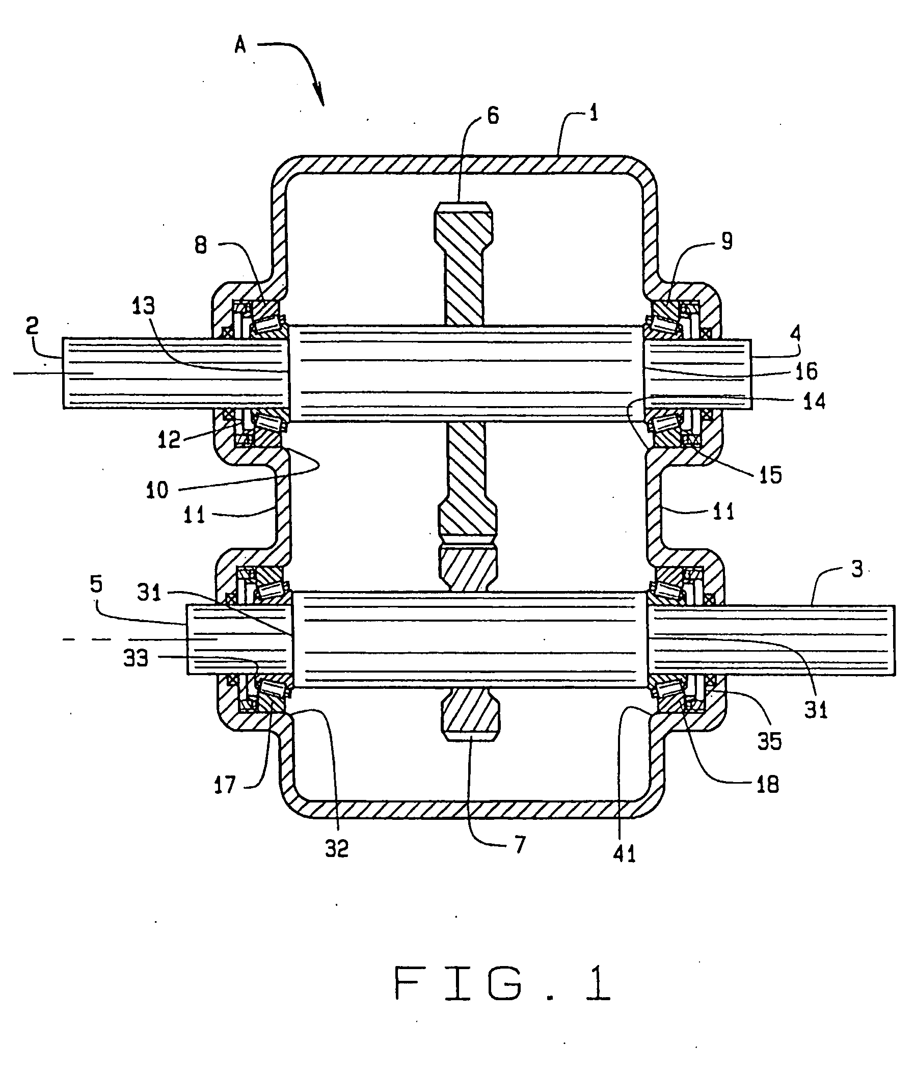
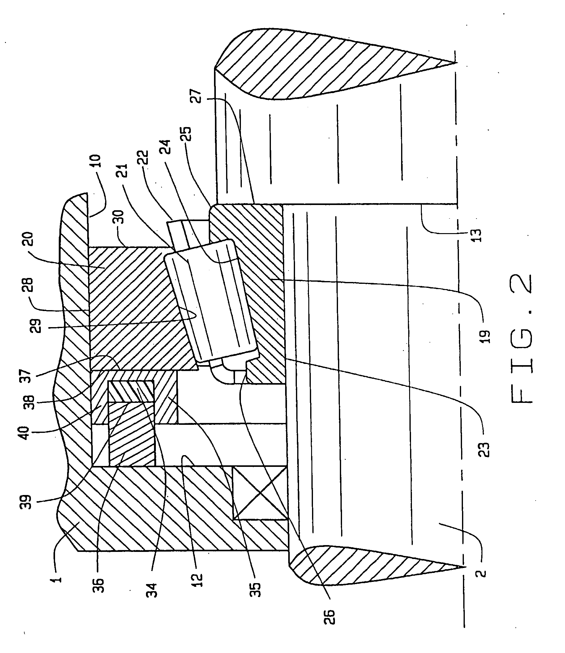
[0022]Referring now to the drawings, one embodiment of the present invention is shown that includes a transmission device A (FIG. 1) having a case 1 that is cast from a lightweight metal such as aluminum alloy. The transmission device A also has an input shaft 2 and an output shaft 3, with each of the two shafts 2 and 3 having an end 4 and 5 respectively. The shafts 2 and 3 support gears 6 and 7, which mesh in different combinations to produce different speed ratios between the input shaft 2 and the output shaft 3. The shafts 2 and 3 are machined from steel, as are the gears 6 and 7 on them.

[0023]The input shaft 2 rotates in two single row tapered roller bearings 8 and 9 that fit around it and within a bore 10 in the wall 11 at each end of the case 1, the bearings 8 and 9 being located between abutments: that is, a shoulder 12 at the end of the bore 10 and another shoulder 13 on the shaft 2. The end 4 of the input shaft 2 rotates on another single row tapered roller bearing 9 locate...


PUM


Abstract

A roller bearing for use in transmission cases (1) made from aluminum alloy or other lightweight materials where the transmission contains a steel shaft (2) which is supported in the case on two directly mounted tapered roller bearings (8,9) so that the two bearings (8,9) confine the shaft (2) both radially and axially. To compensate for the differences in expansion and contraction between the case and the steel shaft (2) as the transmission or transaxle experiences variations in temperature, a race (20) of at least one of the bearings is fitted with a compensating ring (34) having a coefficient of thermal expansion greater than that of the case (1) or shaft (2). As a consequence, the bearings operate at a generally uniform setting over a wide range of temperature variations.

Description

CROSS REFERENCE TO RELATED APPLICATIONS[0001]This application derives and claims priority from U.S. provisional application 60 / 610,934 of Mark A. Joki, filed Sep. 17, 2004 and entitled “Thermal Compensating Bearing” and from U.S. patent application Ser. No. 10 / 899,348 of Mircea Gradu, filed Jul. 26, 2004 and entitled “Bearing Having Thermal Compensating Capability.”TECHNICAL FIELD[0002]This invention relates in general to bearings and more particularly to a bearing having the ability to compensate for differential thermal expansion and contraction between a structure in which the bearing is mounted and a shaft located within the bearing.BACKGROUND ART[0003]In an effort to reduce weight, the cases for various mechanical transmission are constructed from lightweight material such as magnesium or aluminum alloys. However, the shafts which turn in these cases and carry the gears that transmit the torque remain of steel, obviously because steel has great strength and resists wear.[0004]A...

Claims


Application Information

Patent Timeline
Patent Type & Authority Applications(United States)
IPC IPC(8): F16C25/00F16H57/02
CPCF16C25/08F16H57/021Y10T74/2186F16C19/547F16C2361/61F16C19/364
Inventor JOKI, MARK A.GRADU, MIRCEAFOLGER, RUSSELL F.CRICHTON, IV, DAVID D.
Owner THE TIMKEN CO
Why Eureka
Try Eureka