Structure of Discharging Refrigerant For Linear Compressor

a technology of linear compressor and structure, which is applied in the direction of positive displacement liquid engine, piston pump, room acoustics, etc., can solve the problems of increasing noise and vibration, and achieve the effect of reducing and efficiently suppressing the vibration and noise generated by the pulsation of refrigeran

Active Publication Date: 2009-03-26
LG ELECTRONICS INC
View PDF9 Cites 16 Cited by
  • Summary
  • Abstract
  • Description
  • Claims
  • Application Information

AI Technical Summary

Benefits of technology

[0030]In accordance with the present invention, in the structure of discharging the refrigerant for the linear compressor, when the piston is linearly reciprocated inside the cylinder, the refrigerant is compressed and discharged to the discharge cap regardless of generation of the pulsation. As the refrigerant flows from the sub-discharge space with the relatively small volume to the sub-discharge space with the r

Problems solved by technology

That is, even if the pulsation is generated in the high pressure refrigerant, the refrigerant flows through the

Method used


Image

  • Structure of Discharging Refrigerant For Linear Compressor
  • Structure of Discharging Refrigerant For Linear Compressor
  • Structure of Discharging Refrigerant For Linear Compressor

Examples


Embodiment Construction

[0036]A stricture of discharging a refrigerant for a linear compressor in accordance with the preferred embodiments of the present invention will now be described in detail with reference to the accompanying drawings.

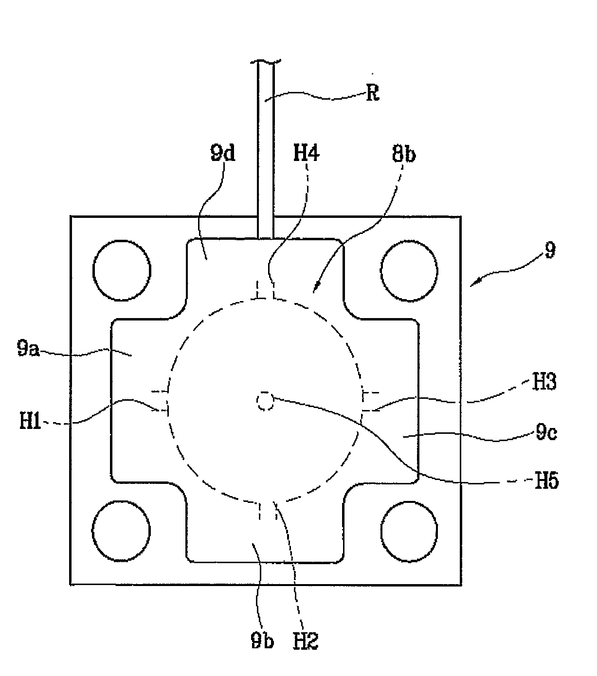
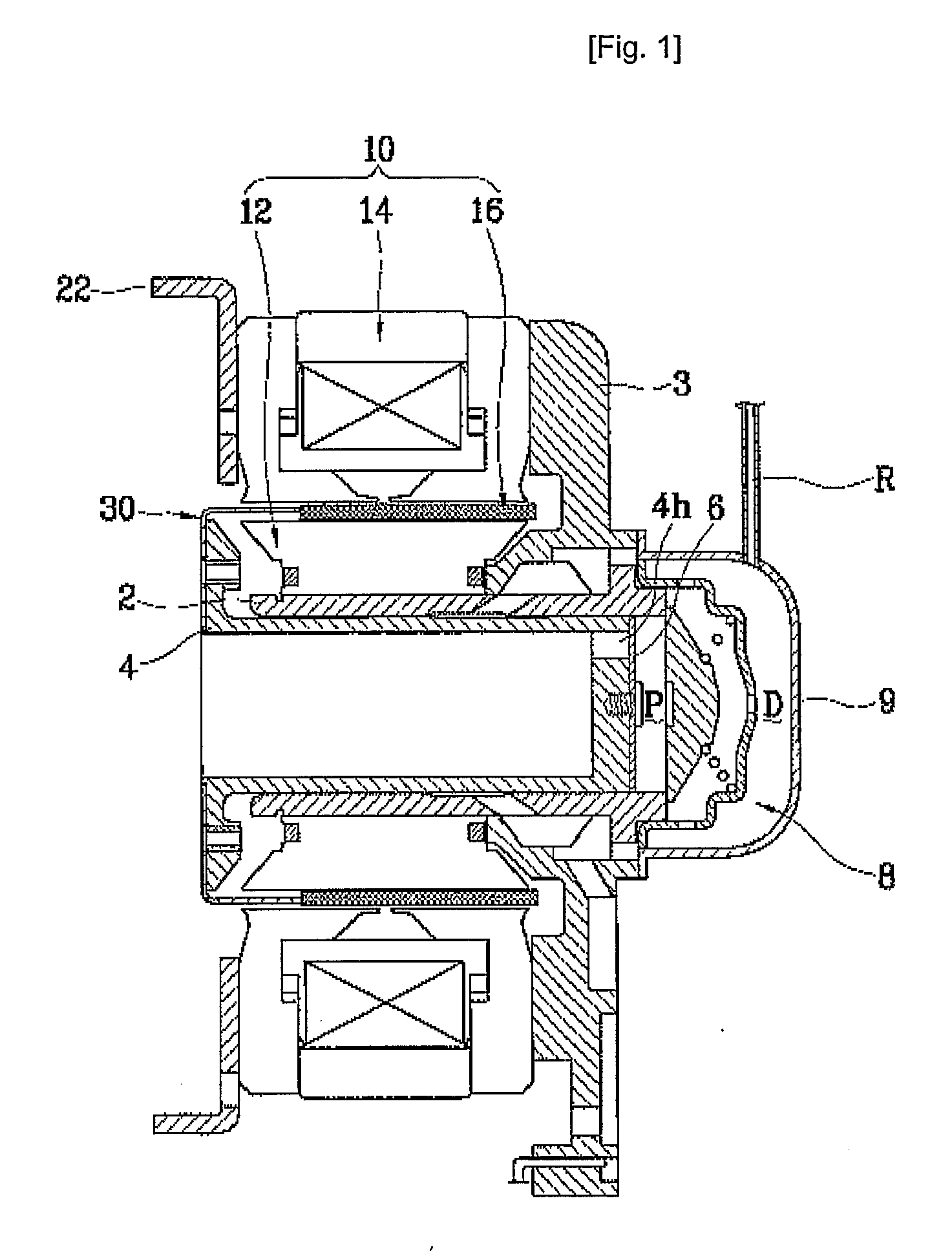
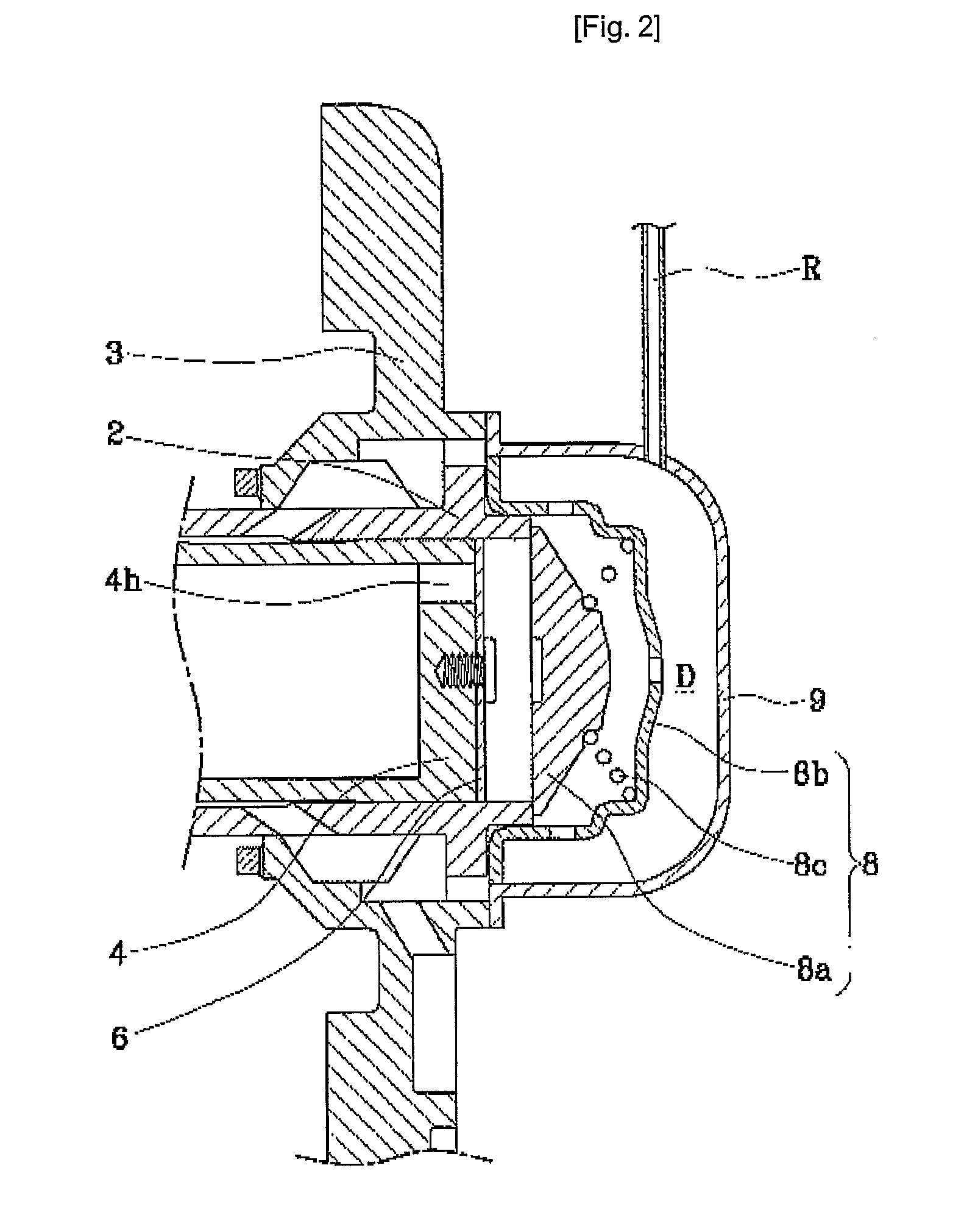
[0037]FIGS. 4 to 6 are a side-sectional view and front views illustrating the linear compressor in accordance with the present invention.

[0038]As illustrated in FIGS. 4 and 5, in the structure of discharging the refrigerant for the linear compressor, one end of a cylinder 2 is fixed to a frame 3, a piston 4 is inserted into the other end of the cylinder 2 and linearly reciprocated inside the cylinder 2, a discharge space D1 is formed at one end of the cylinder 2, a buffering space D2 is formed with an interval from the discharge space D1, a first loop pipe R1 in which the refrigerant flows is installed between the discharge space D1 and the buffering space D2, and a second loop pipe R2 for guiding external discharge of the refrigerant is connected to the buffering space...


PUM


Abstract

The present invention discloses a linear compressor in which a piston is linearly reciprocated inside a cylinder, for sicking a refrigerant into a compression space between the piston and the cylinder, and compressing and discharging the refrigerant, and especially, a structure of discharging the refrigerant for the linear compressor which can reduce a pulsation of a high pressure discharged refrigerant, by making the refrigerant compressed in the compression space flow from a sub-discharge space with a relatively small volume to a sub-discharge space with a relatively large volume in a discharge chamber. As a result, the structure of discharging the refrigerant for the linear compressor can efficiently reduce noise and vibration.

Description

TECHNICAL FIELD[0001]The present invention relates to a linear compressor in which a piston is linearly reciprocated inside a cylinder, for sucking a refrigerant into a compression space between the piston and the cylinder, and compressing and discharging the refrigerant, and more particularly, to a structure of discharging a refrigerant for a linear compressor which can reduce a pulsation of a high pressure discharged refrigerant, by making the refrigerant compressed in a compression space flow from a sub-discharge space with a relatively small volume to a sub-discharge space with a relatively large volume in a discharge cap.BACKGROUND ART[0002]FIG. 1 is a side-sectional view illustrating part of a general linear compressor, and FIGS. 2 and 3 are a side-sectional view and a front view illustrating a conventional structure of discharging a refrigerant for the linear compressor, respectively.[0003]Referring to FIG. 1, in the linear compressor, in a hermetic space of a shell (not show...

Claims


Application Information

Patent Timeline
IPC IPC(8): F04B49/22
CPCF04B35/045Y10S181/403F04B39/102F04B39/0055F04B17/04F04B35/04F04B39/10
Inventor KANG, KYOUNG-SEOKKANG, YANGJUNLEE, JONG-KOOOH, JIN-TAEKLEE, MIN-WOOKIM, KWANG-WOOKSONG, GYE-YOUNG
Owner LG ELECTRONICS INC
Why Eureka
Try Eureka