Supercharge Your Innovation With Domain-Expert AI Agents!

Cable connector, method of connecting a cable connector and a cable

a technology of cable connector and cable connector, which is applied in the direction of coupling contact member, coupling device connection, engagement/disengagement of coupling parts, etc., can solve the problems of undesirable limit of the irradiation direction of the laser beam by the elastic member, complicated structure of the cable connector, etc., and achieve the effect of simple structur

Inactive Publication Date: 2009-03-26
JAPAN AVIATION ELECTRONICS IND LTD +1
View PDF6 Cites 2 Cited by
  • Summary
  • Abstract
  • Description
  • Claims
  • Application Information

AI Technical Summary

Benefits of technology

[0014]In view of the above-mentioned problems, it is an object of this invention to provide a cable connector in which a connecting portion has a simple structure and an irradiation direction of a laser beam is not limited.
[0019]Therefore, an additional elastic member or the like for bringing the end portion of the cable and the terminal into tight contact with each other is not required so that the cable connector has a simple structure.
[0021]According to the first invention, it is possible to provide a cable connector in which a connecting portion has a simple structure and an irradiation direction of a laser beam is not limited.

Problems solved by technology

However, in the above-mentioned structure, the cable connector has a complicated structure because the elastic member is required.
Thus, an irradiation direction of the laser beam is undesirably limited by the elastic member.

Method used


Image

  • Cable connector, method of connecting a cable connector and a cable
  • Cable connector, method of connecting a cable connector and a cable
  • Cable connector, method of connecting a cable connector and a cable

Examples


Embodiment Construction

:

[0033]Now, an exemplary embodiment of this invention will be described in detail with reference to the drawing.

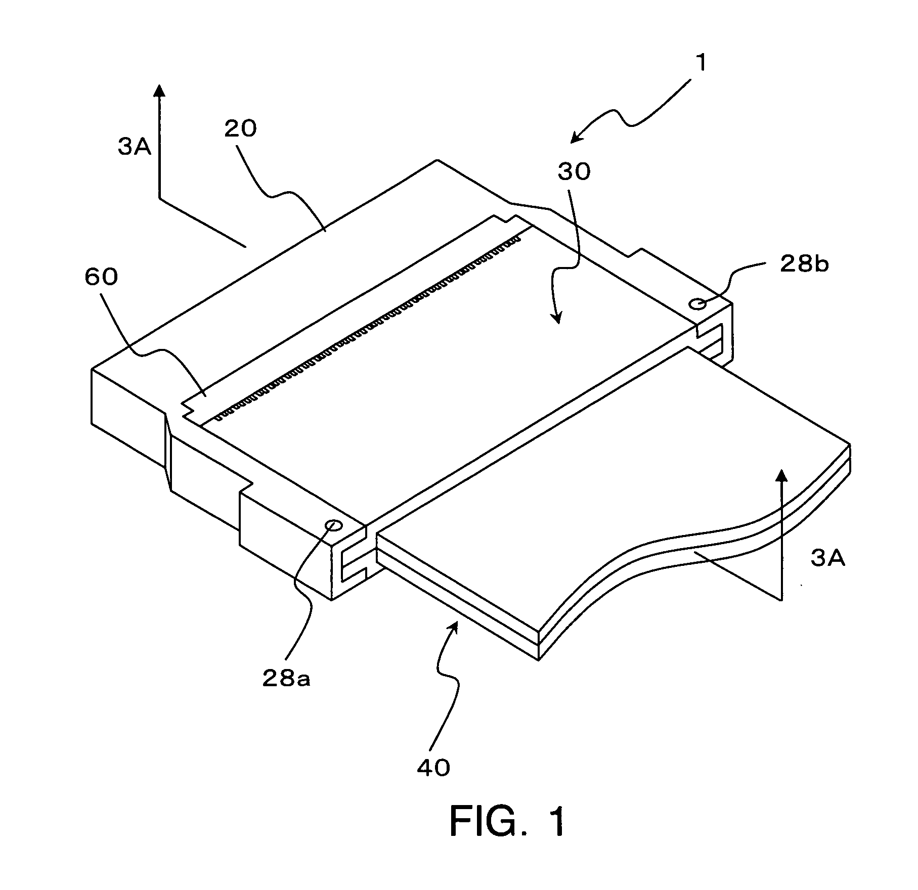
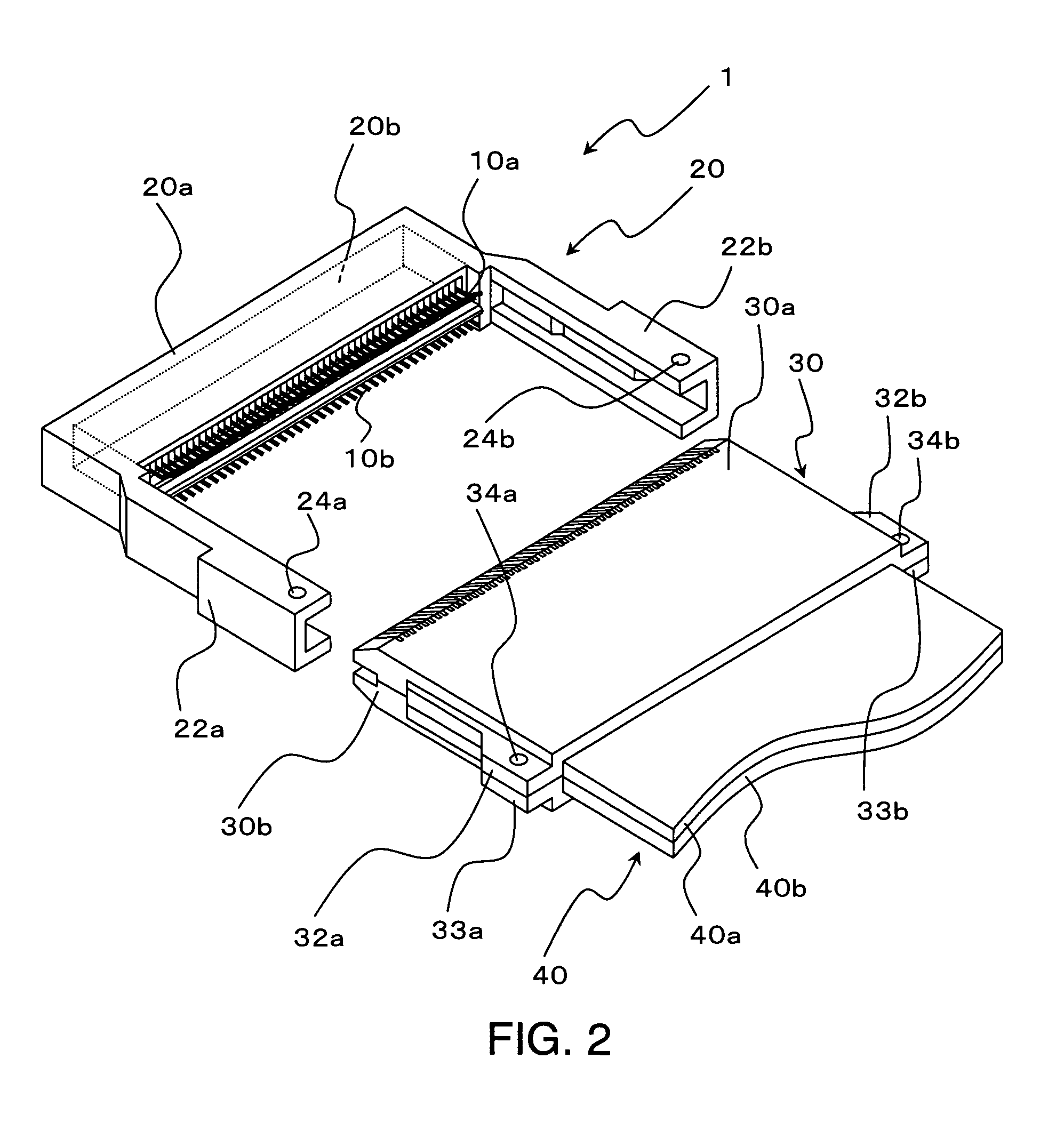
[0034]At first referring to FIGS. 1 and 2, description will be made about a schematic structure of a cable connector 1 according to this embodiment.

[0035]Herein, as the cable connector 1, a cable connector for a flat cable is illustrated by way of example.

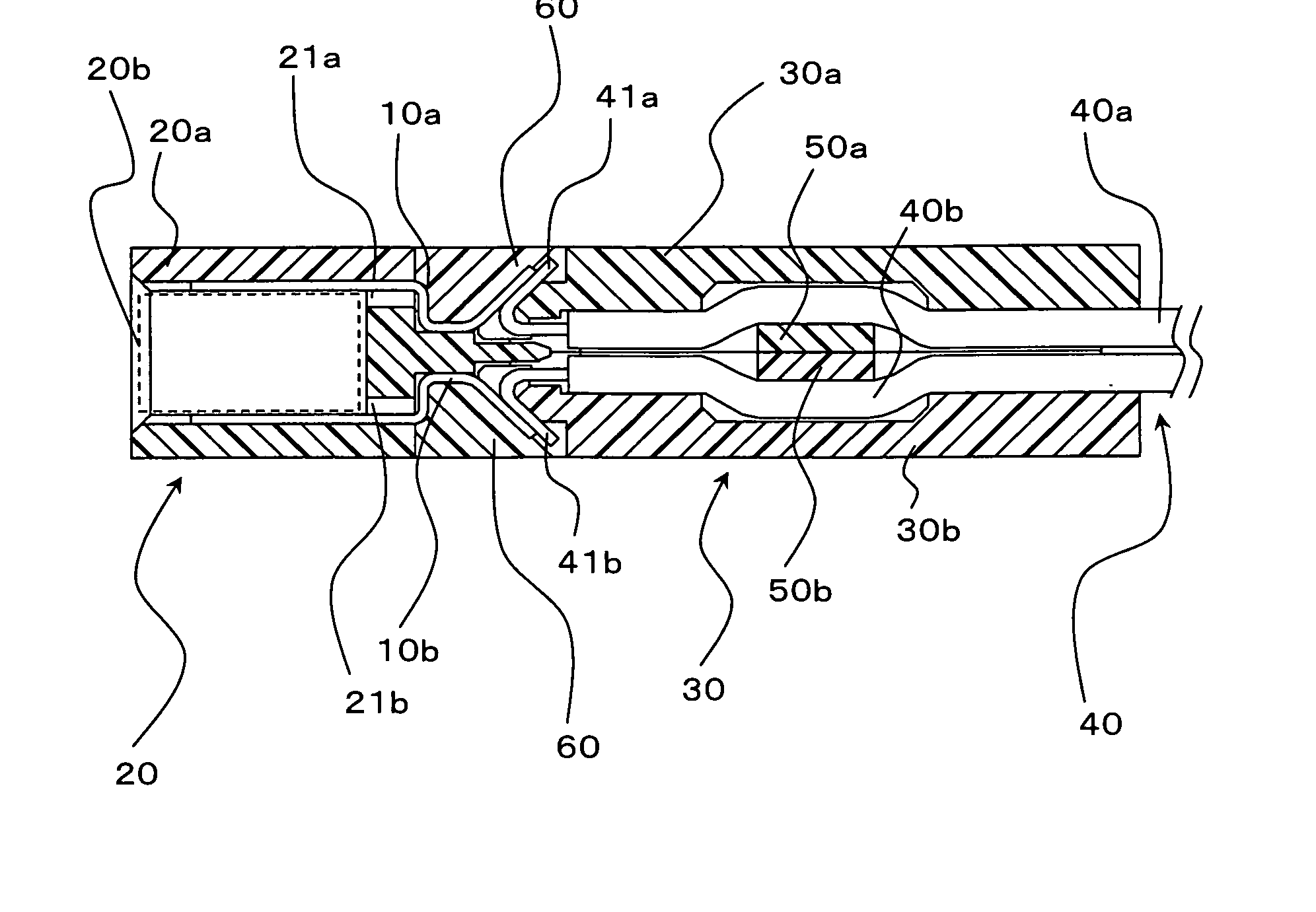
[0036]As shown in FIGS. 1 and 2, the cable connector 1 comprises a cover insulator 30, a base insulator 20, and a plurality of terminals 10a and 10b.

[0037]The cover insulator 30 is adapted to clamp a cable 40. Thus, the cover insulator 30 is a member for holding an end portion of the cable 40.

[0038]The base insulator 20 is adapted to be connected to another connector as a mating connector 81. The base insulator 20 is coupled to the cover insulator 30 so as to surround the cover insulator 30. The base insulator 20 holds the terminals 10a and 10b.

[0039]An insulating member 60 is filled between the base insulator 20 and th...


PUM


Abstract

A cable connector 1 includes a cover insulator adapted to clamp a cable. The cable has an end portion bent by a bending angle α. The cover insulator is coupled to a base insulator. The base insulator holds a terminal having an end portion bent by a bending angle β. Herein, the angles α and β satisfy the relationship given by β<π−α(rad) so that the end portion of the cable is pressed by the end portion of the terminal.

Description

[0001]This application is based upon and claims the benefit of priority from Japanese patent application No. 2007-245484, filed on Sep. 21, 2007, the disclosure of which is incorporated herein in its entirety by reference.BACKGROUND OF THE INVENTION [0002]The present invention relates to a cable connector and a method of connecting a cable connector and a cable.[0003]For installation of electrical equipment in transport machines such as automobiles, computer wiring, and the like, cables having a variety of structures are used. Generally, cable connectors for connection between cables are provided.[0004]For example, a cable connector comprises a cover insulator adapted to clamp an end portion of a cable and a base insulator having a terminal (contact) to be connected to another connector as a mating connector.[0005]With this structure, the cable connector and the cable are connected by coupling the cover insulator and the base insulator and connecting the end portion of the cable and...

Claims


Application Information

Patent Timeline
IPC IPC(8): H01R13/62H01R13/58
CPCH01R12/592H01R4/029
Inventor NAKAZAWA, KATSUHIKOYAMAUCHI, MASAHIRO
Owner JAPAN AVIATION ELECTRONICS IND LTD
Features
  • R&D
  • Intellectual Property
  • Life Sciences
  • Materials
  • Tech Scout
  • Unparalleled Data Quality
  • Higher Quality Content
  • 60% Fewer Hallucinations
Learn More