
Intervertebral implant

a technology of intervertebral implants and implants, which is applied in the field of intervertebral implants, can solve the problems of difficult movement of parts out of the insertion position into the working position inside the body, injuries can also occur, and the difficulty of implant insertion into the body is high

Inactive Publication Date: 2009-03-26
AESCULAP AG
View PDF10 Cites 11 Cited by
  • Summary
  • Abstract
  • Description
  • Claims
  • Application Information

AI Technical Summary

Benefits of technology

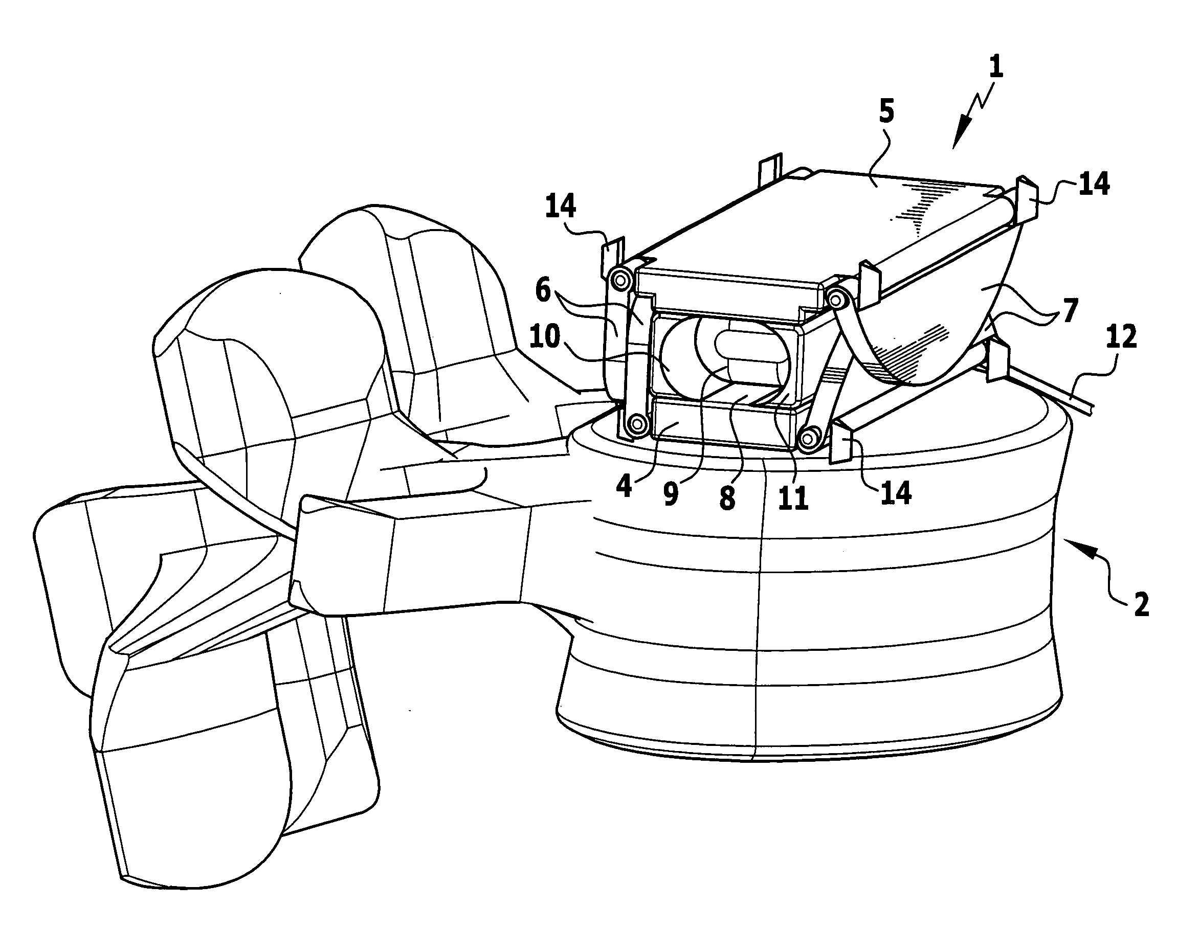
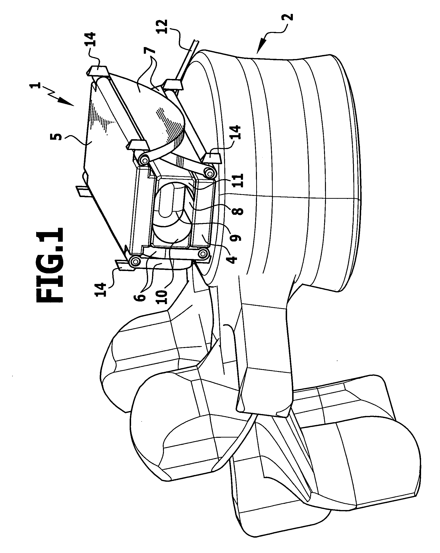
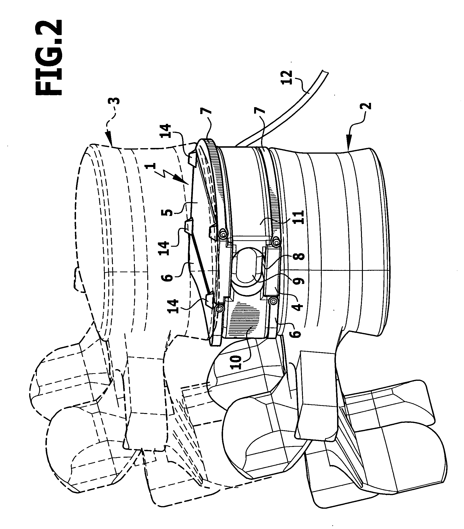
[0011]Such an expansion body, which can be in the form of a bellows or a balloon, for example, can be arranged in the implant in a simple manner, and when in unfilled state such an expansion body assumes a minimum volume, so that the structural size of the implant can remain practically unchanged. By filling the expansion body with a flowable medium, e.g. a gas or a liquid, in particular with a sodium chloride solution, the volume of the expansion body can be increased, and because of its increased volume this enlarged expansion body moves the parts of the abutment surface out of the insertion position into the working position. In this case, different kinematic arrangements are possible, e.g. the parts can be displaceable parallel to one another, the expansion body then displaces the parts accordingly when increasing in volume.
[0014]In a particularly preferred embodiment of the invention, it is provided that besides the expansion body it has a core composed of a swellable material, which has a low volume in a state low in liquid and upon liquid absorption increases its volume, and that after liquid absorption with increased volume the core supports the parts of the abutment surface in the working position in such a manner that they are prevented from moving back into the insertion position.
[0018]In a preferred embodiment, it is provided that the expansion body has at least one outlet for the flowable material, which is arranged in such a manner that the flowable medium discharging from it impinges against the swellable low-liquid material of the core. In this way, as a result of the flowable medium discharging from the outlet, the flowable medium, in particular a sodium chloride solution, can act on the swellable material of the core. This accelerates the absorption of liquid of the swellable material and thus its increase in volume.
[0022]It is possible, in principle, that an intervertebral implant only has such an abutment surface on one side, but the intervertebral implant is generally configured so that an abutment surface comprising a plurality of parts is respectively provided on opposite sides of the intervertebral implant, and that the expansion body or bodies and when applicable the core of swellable material are arranged in the space between the two abutment surfaces. This results in a particularly compact arrangement of the intervertebral implant, in particular in the insertion position of the parts of the abutment surface.

Problems solved by technology

However, the relatively large configuration of the abutment surface causes difficulties during insertion of the implant into the body, in particular during insertion through a dorsal or dorsal-lateral access point.
However, movement of the parts out of the insertion position into the working position inside the body is difficult.
This movement must be performed, for example, by instruments inserted into the body, and this is difficult, and in this case injuries can also occur because of the forces employed during this.
However, the structure of the implant is complicated as a result of this and this also leads to increased dimensions.

Method used


Image

  • Intervertebral implant
  • Intervertebral implant
  • Intervertebral implant

Examples


Embodiment Construction

[0033]The intervertebral implant 1 shown in the drawing is used as a replacement for a removed intervertebral disc between two adjacent vertebral bodies 2, 3 and is respectively supported against the faces of these two vertebral bodies 2, 3 facing towards one another.

[0034]For this, the intervertebral implant has two spaced central abutment plates 4, 5 running parallel to one another, which have a substantially rectangular cross-section and on their opposite longitudinal sides two lateral abutment plates 6 and 7 are respectively disposed to pivot around an axis running parallel to the longitudinal sides. A respective central abutment plate 4 or 5 and the abutment plates 6 and 7 disposed thereon jointly form an end plate of the intervertebral implant 1. In this case, the two end plates are substantially the same in configuration and only differ in that one end plate is slightly wider than the other, so that the lateral abutment plates 6, 7 of the two end plates lie one on top of the ...


PUM

PropertyMeasurementUnit
volumeaaaaaaaaaa
resorbableaaaaaaaaaa
compressive forcesaaaaaaaaaa

Abstract

In an intervertebral implant with at least one abutment surface formed from a plurality of parts for a vertebral body, which parts are movable relative to one another between an insertion position, in which the intervertebral implant has a small cross section, and a working position, in which the intervertebral implant has a larger cross section and in which the parts jointly form the abutment surface, and with an adjusting means for moving the parts out of the insertion position into the working position, in order to provide an uncomplicated structure having small dimensions, it is proposed that the adjusting means have at least one expansion body, which increases in volume when filled with a flowable medium and thus moves the parts into the working position.

Description

[0001]This application is a continuation of international application number PCT / EP2007 / 002675 filed on Mar. 27, 2007.[0002]The present disclosure relates to the subject matter disclosed in international application PCT / EP2007 / 002675 of Mar. 27, 2007 and German application number 10 2006 016 985.9 of Apr. 6, 2006, which are incorporated herein by reference in their entirety and for all purposes.BACKGROUND OF THE INVENTION[0003]The invention relates to an intervertebral implant with at least one abutment surface formed from a plurality of parts for a vertebral body, said parts being movable relative to one another between an insertion position, in which the intervertebral implant has a small cross-section, and a working position, in which the intervertebral implant has a larger cross-section and in which the parts jointly form the abutment surface, and with an adjusting means for moving the parts out of the insertion position into the working position.[0004]In the case of interverteb...

Claims


Application Information

Patent Timeline
Patent Type & Authority Applications(United States)
IPC IPC(8): A61F2/44
CPCA61F2/442A61F2220/0091A61F2002/30075A61F2002/30471A61F2002/30505A61F2002/3052A61F2002/30563A61F2002/30579A61F2002/30581A61F2002/4635A61F2002/485A61F2210/0004A61F2210/0061A61F2220/0025A61F2002/30062A61F2/484
Inventor BEGER, JENS
Owner AESCULAP AG
Learn More