An improved sleeve expansion device

An improved and sleeve-expanding technology, applied in the direction of expanding the mandrel, can solve the problems of complex structure, difficult operation, and small expansion and contraction of the expansion sleeve, and achieve the effects of reducing production costs, improving production efficiency, and increasing expansion and contraction.

Active Publication Date: 2018-10-02
HENGDIAN GRP DMEGC MAGNETICS CO LTD
View PDF8 Cites 0 Cited by
  • Summary
  • Abstract
  • Description
  • Claims
  • Application Information

AI Technical Summary

Problems solved by technology

[0003] The purpose of the present invention is to solve the problems of complex structure, difficult operation, high cost and small amount of expansion in the prior art, and provide an improved expansion device, which has the advantages of simple structure, convenient operation and large amount of expansion. It can meet the requirements of mass and rapid production of motor casings, effectively improve production efficiency and greatly reduce production costs

Method used


Image

  • An improved sleeve expansion device
  • An improved sleeve expansion device
  • An improved sleeve expansion device

Examples


Embodiment 1

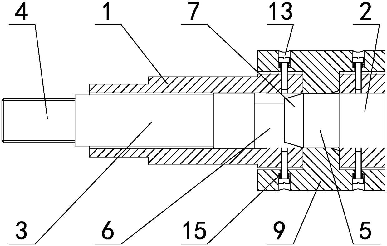
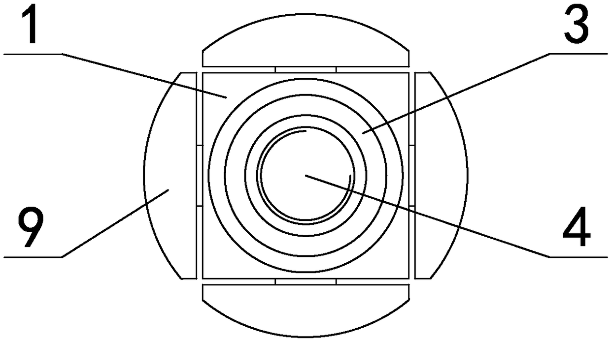
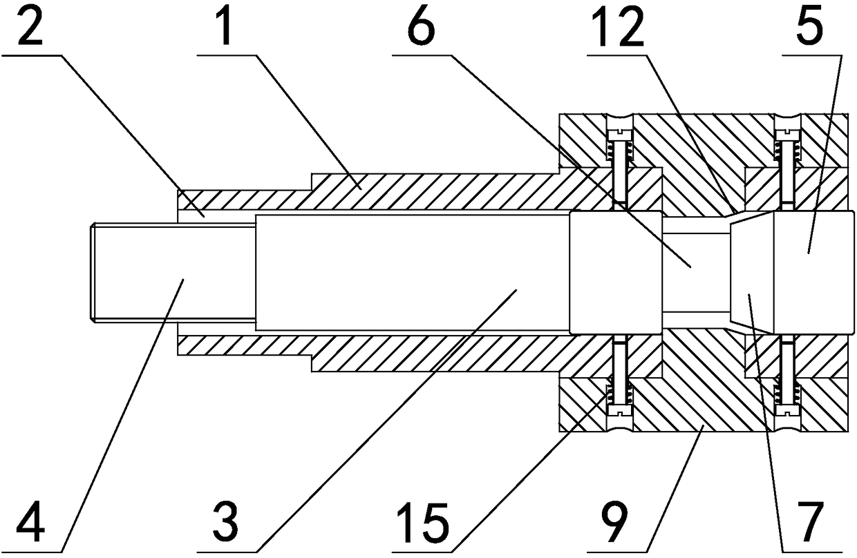
[0028] in such as figure 1 figure 2 In the shown embodiment 1, an improved expansion sleeve device is used for the processing of the motor casing, including the shaft sleeve 1 whose rear end can be fixed with the machine tool (see Figure 5 ), the center of the sleeve is provided with a shaft hole 2 (see Figure 5 Figure 6 ), the shaft hole is provided with a cylindrical telescopic shaft 3 that can move axially along the shaft hole (see Figure 7 ), the telescopic shaft includes a connecting part 4 at the rear end and an extruding part 5 at the front end, the connecting part is provided with an external thread that can be connected with the piston shaft of the telescopic cylinder; the rear side of the extruding part is provided with a necking section 6, The diameter of the necking section is smaller than the diameter of the extrusion part, and the guide tapered surface 7 is guided between the extrusion part and the necking section. A number of mounting surfaces 8 are unif...

Embodiment 2

[0031] Embodiment 2 A fine-tuning hole 17 is provided in the center of the front end of the extruding part of the telescopic shaft (see Figure 10 ), the fine-tuning hole is a threaded hole, the depth of the fine-tuning hole is greater than the axial length of the extruded part, the outer wall of the fine-tuning hole is provided with radial through-slots 18, the number of radial through-slots is consistent with the number of mounting surfaces and its The center plane is on the symmetrical center plane of two adjacent mounting surfaces (there are four radial through slots in this embodiment and the center plane is on the same radial plane as the edge of the positive prism), and there are fine-tuning bolts in the fine-tuning hole 19. There is a lock nut 20 between the fine-tuning bolt and the front end of the extrusion part (see Figure 11 ), and the rest are the same as in Example 1.

[0032] The shaft sleeve of the present invention is fixed on the chuck of the machine tool. ...


PUM


Abstract

The invention discloses an improved swelling sleeve device which is used for machining of a motor case. The improved swelling sleeve device comprises a shaft sleeve; the rear end of the shaft sleeve can be fixed to a machine tool; a shaft hole is formed in the center of the shaft sleeve, and is internally provided with a telescopic shaft capable of moving axially along the shaft hole; the telescopic shaft comprises a connecting part at the rear end and an extrusion part at the front end; a reduced section is arranged on the rear side of the extrusion part; a plurality of swelling blocks are arranged on the peripheral surface of the front end of the shaft sleeve; the extrusion part abuts against the swelling blocks through propping columns that are arranged on the swelling blocks and penetrate into the shaft hole; and an elastic resetting mechanism is arranged between the shaft sleeve and each swelling block. The problems that a swelling sleeve in the prior art is complex in structure, high in operation difficulty, high in cost and small in expansion quantity are solved effectively; the production efficiency can be improved effectively; the production cost can be reduced; and the improved swelling sleeve device has very high practical value.

Description

technical field [0001] The invention relates to the technical field of mechanical processing, in particular to an improved sleeve expanding device used for processing motor casings. Background technique [0002] In a factory that produces motor casings, a large part of the processing is to cut steel pipes (workpieces) for processing casings, and cutting pipes requires turning the outer diameter or turning the end face. In the existing processing process, the material is directly blanked. The pipe needs to go through multiple processes such as pipe cutting→inner angle chamfering→finishing both ends of the car. Since the expansion and contraction of the existing expansion sets is very small (usually only 0.3 to 0.4 mm), the pipe after blanking It is necessary to go through the inner corner chamfering process before inserting the expansion sleeve mold for the end face operation, which is time-consuming and labor-intensive. However, most expansion sleeve devices with large expan...

Claims


Application Information

Patent Timeline
Patent Type & Authority Patents(China)
IPC IPC(8): B23B31/40
CPCB23B31/40
Inventor 王旭东沈睿
Owner HENGDIAN GRP DMEGC MAGNETICS CO LTD
Why Eureka
Try Eureka