Implement lift apparaturs control system position sensing

a control system and lift technology, applied in adaptive control, adjusting devices, instruments, etc., can solve the problems of excessive cost, limited use and frequent subjection of sensors or sensor systems to the use of travel sensors,

Active Publication Date: 2009-03-26
DEERE & CO
View PDF6 Cites 32 Cited by
  • Summary
  • Abstract
  • Description
  • Claims
  • Application Information

AI Technical Summary

Benefits of technology

[0008]In addition, an additional reference sensor in the form of a gyroscope or rotational speed sensor may be positioned on the vehicle in order to improve the reference measurement and / or in order to perform error correction. It is therefore possible to compensate more accurately errors which creep in owing, for example, to the different positioning of acceleration meters and reference sensors. A three-axle gyroscope with integrated acceleration pickup can measure, for example, all 6 degrees of freedom of a vehicle as a reference. This has the advantage that the acceleration sensors which are positioned on the implements permit a detection of a position at which all the translatory and rotational errors can be compensated.
[0009]In a preferred embodiment, at least a second acceleration sensor is positioned on the lifting apparatus and / or on the implement, with the result that at least two or more acceleration sensors are provided and they are placed or connected on the vehicle in reference to the reference sensor. In this way it is possible for the position of both the lifting apparatus and of the implement as well as of further components on the vehicle which are provided with acceleration sensors to be determined by sensor independently of one another and moved to.
[0011]The front loader preferably comprises a tool receptacle to which the implement or the front loader tool can be coupled, wherein the at least one acceleration sensor or the second acceleration sensor is positioned on the tool receptacle. It is therefore possible, for example, to provide a rocker of the front loader with an acceleration sensor in order to sense or control or move to the position of the lifting mechanism, and to provide a further acceleration sensor on the tool receptacle, with which acceleration sensor the position of the tool is sensed. As a result, the same acceleration sensor, specifically the sensor which is positioned on the tool receptacle, can be used to determine the position of any tool which is coupled to the tool receptacle. It is therefore possible to avoid any tool having to be provided with its own acceleration sensor. In a further preferred refinement of the invention, the lifting apparatus comprises a trailer apparatus, in particular as a three-point trailer apparatus, and the implement comprises a trailer unit which can be coupled to the trailer apparatus. It is therefore possible, for example, to determine and control electronically the position of any desired trailer unit or implement which can be coupled to a three-point trailer device. Said trailer unit or implement may be, for example, a soil working device or a field sprayer trailer.
[0012]The lifting apparatus may also be an implement linkage for a combine header, and the implement may be a combine header. For example, a mowing / reaping header, a machine for picking up harvested material, a cutting mechanism, a reel or the like can be coupled to an implement linkage on the vehicle, and in this way it is possible to control the positioning of the implement at a specific predefinable distance from the ground.
[0016]Alternatively, the vehicle may be a construction machine, in particular as a wheel loader vehicle, wherein the lifting apparatus comprises a loading apparatus, and the implement comprises a shovel. In this case, it is possible to implement, for example, tracking of the shovel, with the result that during excavation and transportation operations it is ensured that the shovel is guided parallel to the surface of the ground irrespective of the structure of the ground and the position of the construction machine, and changes in the position of the construction machine (when there are unevennesses in the ground or in the case of spring movements) can be compensated, with the result that changes in the pivoting angle of the shovel which are caused by this and associated loss of bulk material can be avoided.
[0017]Alternatively, the vehicle may be a telescopic loader vehicle, wherein the lifting apparatus comprises a telescopic extension arm to which an implement can be coupled via a tool receptacle. In this context it is possible, for example, to carry out tracking of the implement, with the result that during loading and transportation operations it is ensured that the implement is guided parallel to the surface of the ground irrespective of the structure of the ground and the position of the construction machine, and changes in the position of the construction machine (when there is unevenness in the ground or in the case of spring movements) can be compensated, with the result that changes in the pivoting angle of the implement which are caused by this are avoided. In addition, it also is possible, for example, to control the position of the telescopic extension arm as a function of the length of the telescopic extension arm, or for automated position following to be carried out for the telescopic extension arm as a function of predefined operator control steps so that, for example when lifting the extension arm, it is moved to a predefinable first position, and during lowering it it is moved to a predefined second position.

Problems solved by technology

The systems described in these articles are limited to the use of travel sensors, speed sensors, inclination sensors, contact sensors or to potentiometers, magneto-resistive length sensors in hydraulic cylinders, open-loop control approaches (characteristic diagram measurement of valves with referencing) as well as I / O control systems with final position switches or Hall sensors.
The disadvantages of such known approaches are that, owing to their arrangement on the vehicle, the aforesaid sensors or sensor systems are frequently subjected to damage, are excessively costly or are not yet mature technology, in particular with respect to the accuracy and sensitivity of some sensors or sensor systems.
For example, moving parts in the sensors or in the sensor system and the sensors or the sensor system itself often have to be protected, only achievable with large expenditure, owing to their unfavourable arrangement on the vehicle or on the lifting apparatus.
It is disadvantageous that the disclosed system is based on the implementation of iteration steps and therefore requires a large amount of complex computing work and in addition is inaccurate and only refers to parameter data relating to the vertical.

Method used


Image

  • Implement lift apparaturs control system position sensing
  • Implement lift apparaturs control system position sensing
  • Implement lift apparaturs control system position sensing

Examples


Embodiment Construction

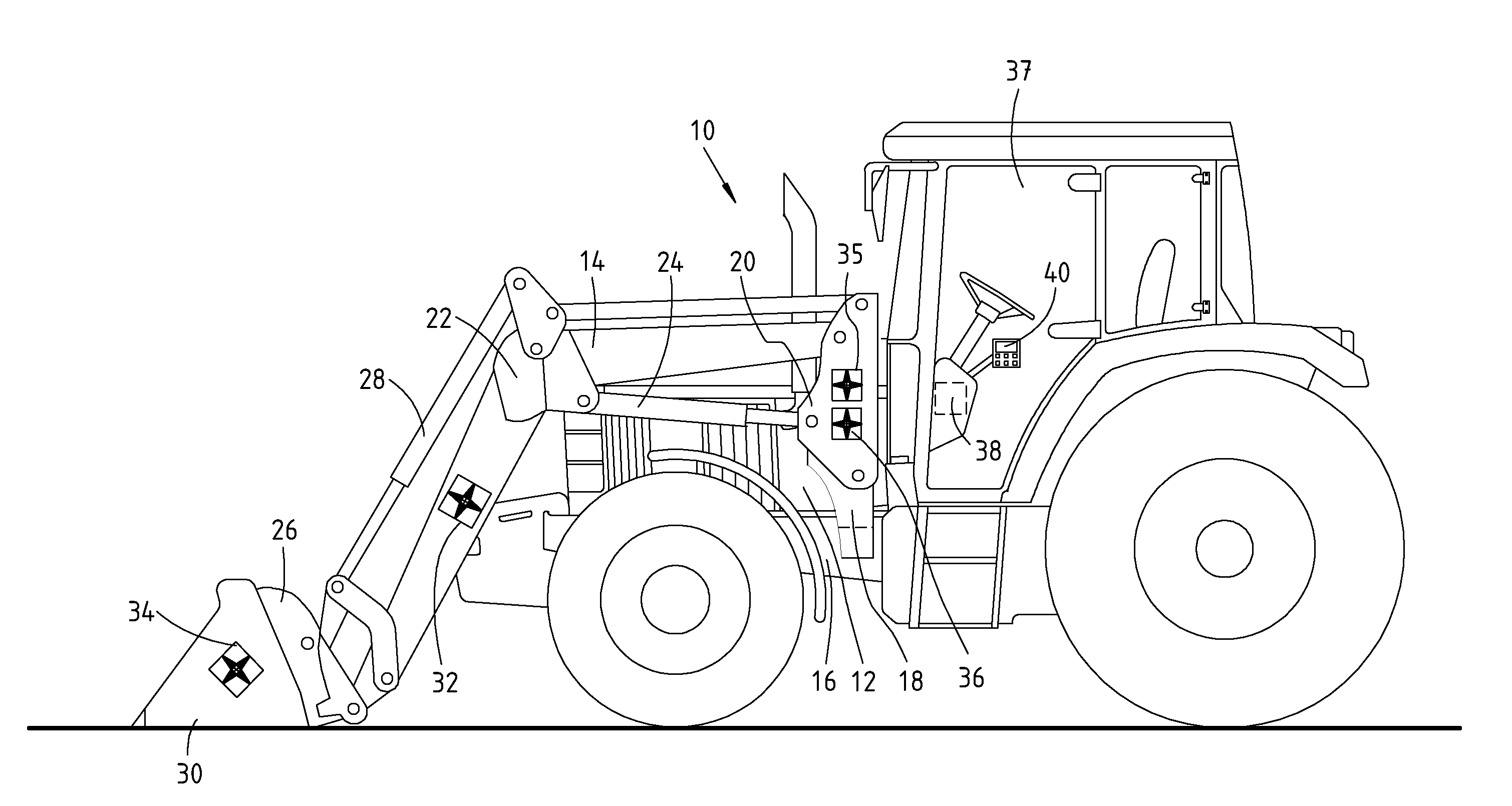
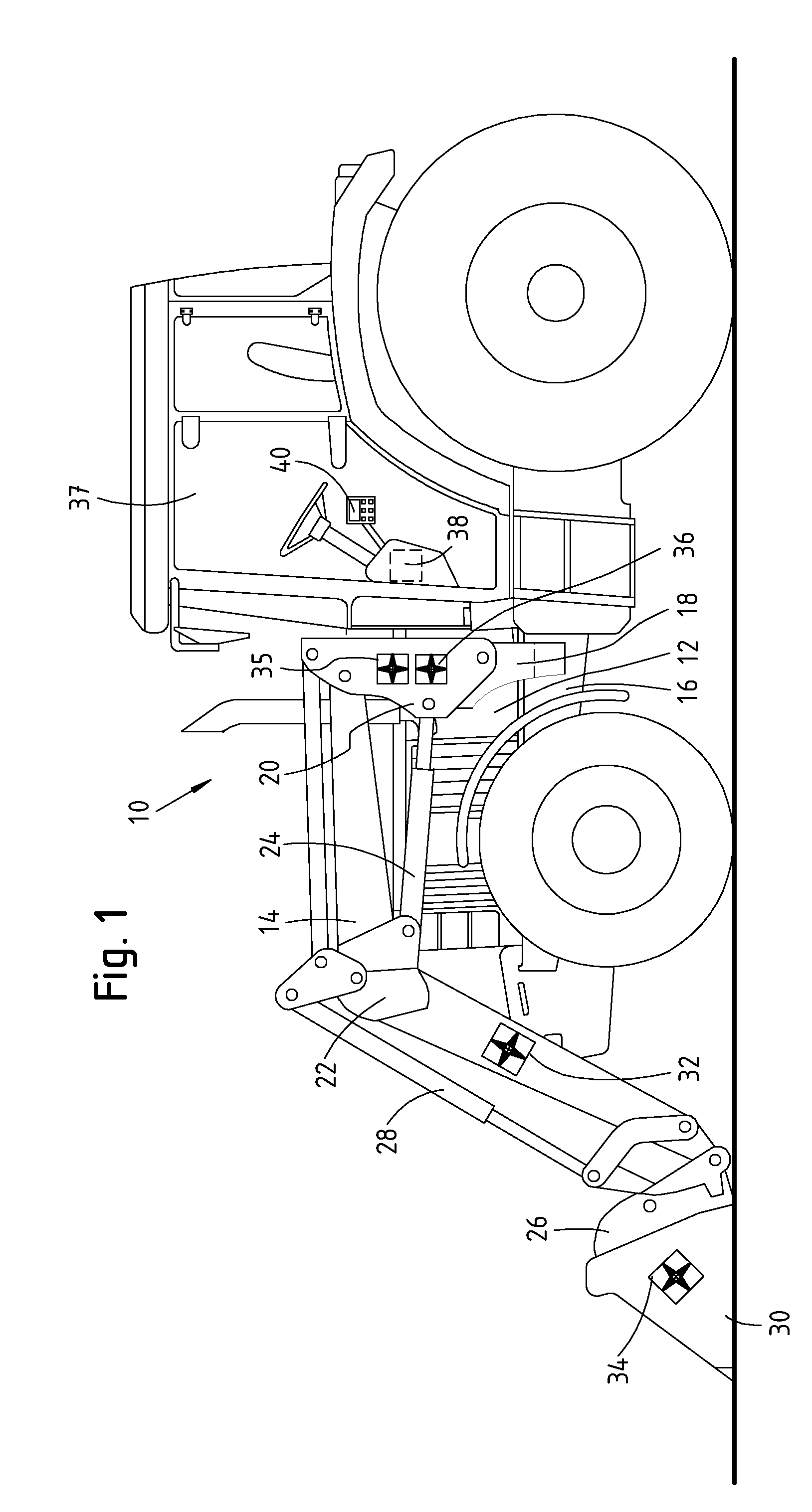
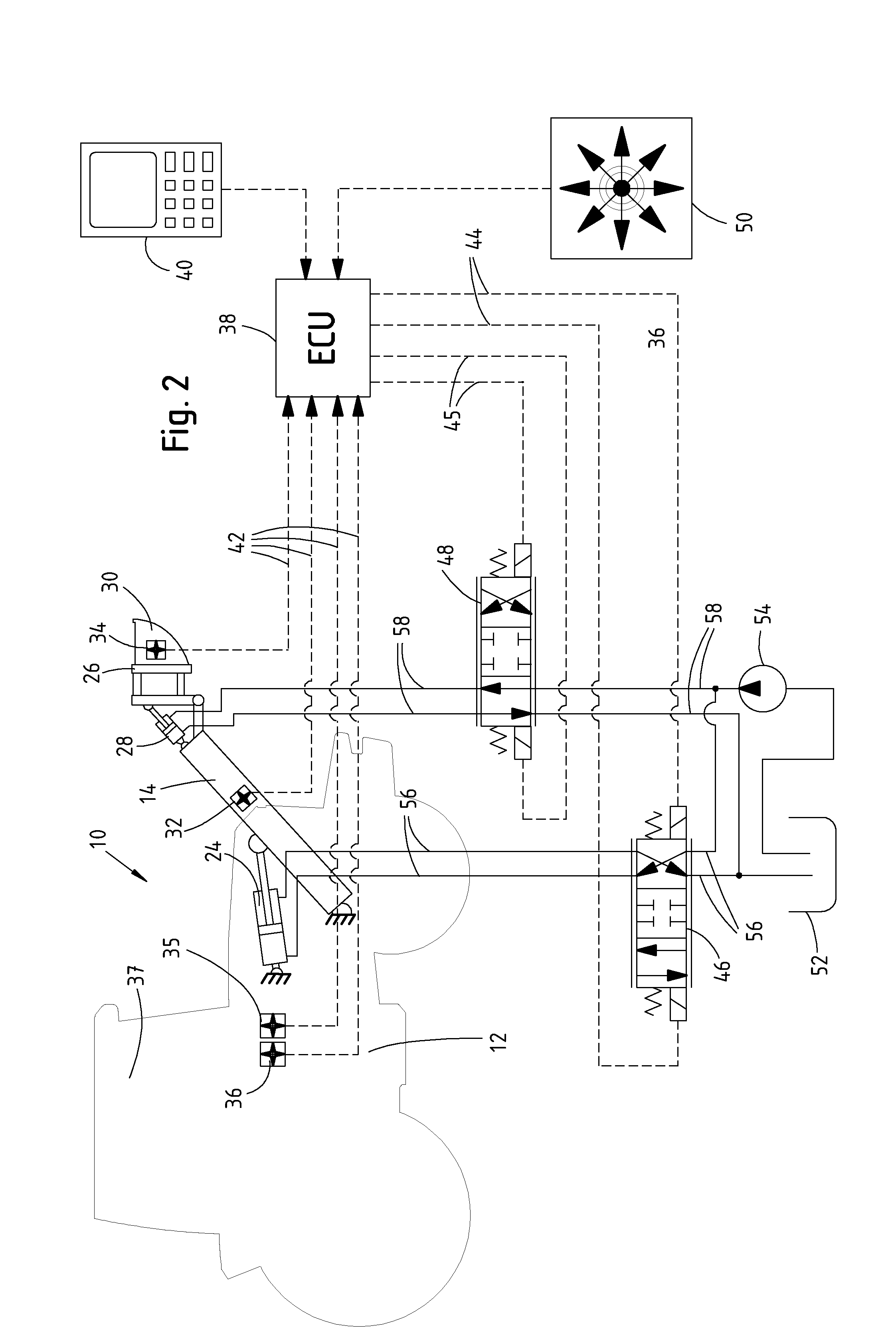
[0025]FIGS. 1 and 2 show an agricultural machine 10 with a tractor 12 with a lifting apparatus in the form of a front loader 14 and an implement coupling control system 13. The front loader 14 is coupled to the tractor 12 by means of a bracket 18 which is connected to a frame 16 of the tractor and to a connecting pole 20. The front loader 14 has a rocker 22 which is coupled in a pivotable fashion to the connecting pole 20 by means of hydraulic cylinders 24. A tool receptacle 26, which is pivotally coupled to the rocker 22 by means of a further hydraulic cylinder 28, is arranged at the front end of the rocker 22. An implement or tool in the form of a loader shovel 30 is attached to the tool receptacle 26. The front loader 14 is provided in the region of the rocker 22 with a first acceleration sensor 32. A further acceleration sensor 34 is provided in the region of the loader shovel 30. In addition, the tractor 12 is provided with an acceleration sensor which constitutes a reference s...


PUM


Abstract

An agricultural machine includes a lifting apparatus to which an implement or tool is attached. A control system controls the lifting apparatus in response to sensed parameters and operator inputs. The control system includes a first acceleration sensor positioned on the lifting apparatus and / or on the implement, and at least one reference acceleration sensor positioned on the vehicle. The control system includes an electronic control unit which processes acceleration signals from the acceleration sensors and generates a lift apparatus or implement position signal as a function thereof.

Description

FIELD OF THE INVENTION[0001]The present invention relates to an implement coupling control system which utilizes acceleration sensors for position sensing.BACKGROUND OF THE INVENTION[0002]Many types of vehicles have control systems which control a hitch or lifting apparatus to which an implement or tool is attached. With such a control system it is known to sense or determine the position of the lifting apparatus which is coupled to the vehicle, or to determine the position of implements or tools which are coupled to the lifting apparatus. Such a lifting apparatus normally includes an actuator or motor, such as hydraulic cylinders which extend between a movable linkage and an attachment frame of the vehicle. For example, front loaders have movable linkages which are a pair of rockers which are pivotably coupled to a bracket which is connected to the frame of an agricultural tractor. The movable linkage of a front loader can be coupled at its free end to the tool, for example to a sh...

Claims


Application Information

Patent Timeline
Patent Type & Authority Applications(United States)
IPC IPC(8): G05B13/00
CPCA01B63/1117G01C21/16E02F3/432B66F9/22
Inventor PETERS, OLE
Owner DEERE & CO
Why Eureka
Try Eureka