Packer for Repairing Crack in Concrete Body

a concrete body and crack technology, applied in the field of concrete body crack repair packaging, can solve the problems of increasing labor costs due to post-process, elongating construction time, and cracks in concrete bodies, and achieves the effects of shortening the time for crack repair, reducing labor costs, and reducing labor costs

Inactive Publication Date: 2009-04-02
HWANG BYEONG KWON
View PDF6 Cites 3 Cited by
  • Summary
  • Abstract
  • Description
  • Claims
  • Application Information

AI Technical Summary

Benefits of technology

[0010]A packer for repairing a crack in a concrete body of the present invention includes an injection main body including an inflow route formed therethrough in the longitudinal direction, two extension units, each having a trapezoidal section, formed at a designated interval at one end of the injection main body, and a nipple part formed at the other end of the injection main body, and a soft sleeve inserted into the extension units, and is inserted into a fixing hole formed in the concrete body along the crack by drilling, in which the soft sleeve maintains its original position and the injection main body is partially pushed out when a resin solution is injected into the injection main body and is returned to a proper position when the injection of the resin solution is stopped, thus allowing the soft sleeve to be uniformly stuck to the fixing hole in the circumferential direction within the range where

Problems solved by technology

Usually, concrete bodies are cracked due to various reasons, such as repetition of drying, shrinking, and freezing and melting of concrete, infiltration of salt water or acid materials and corrosion iron reinforcing rods.
Thus, such a packer elongates the construction time, and increase labor costs due to a post process.
Further, when the nut is excessively tightened, the rubber sleeve is bent and str

Method used


Image

  • Packer for Repairing Crack in Concrete Body
  • Packer for Repairing Crack in Concrete Body
  • Packer for Repairing Crack in Concrete Body

Examples


first embodiment

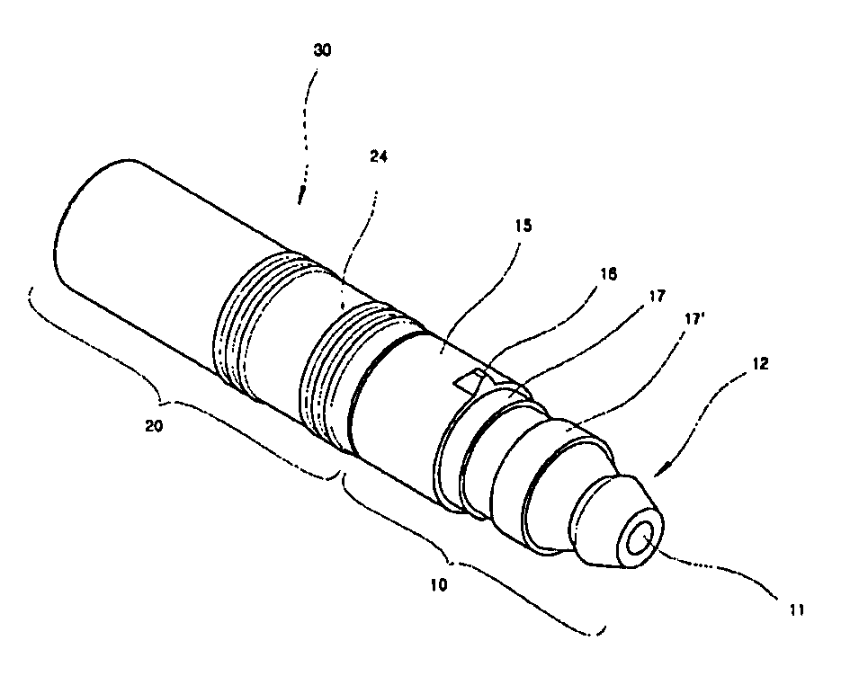
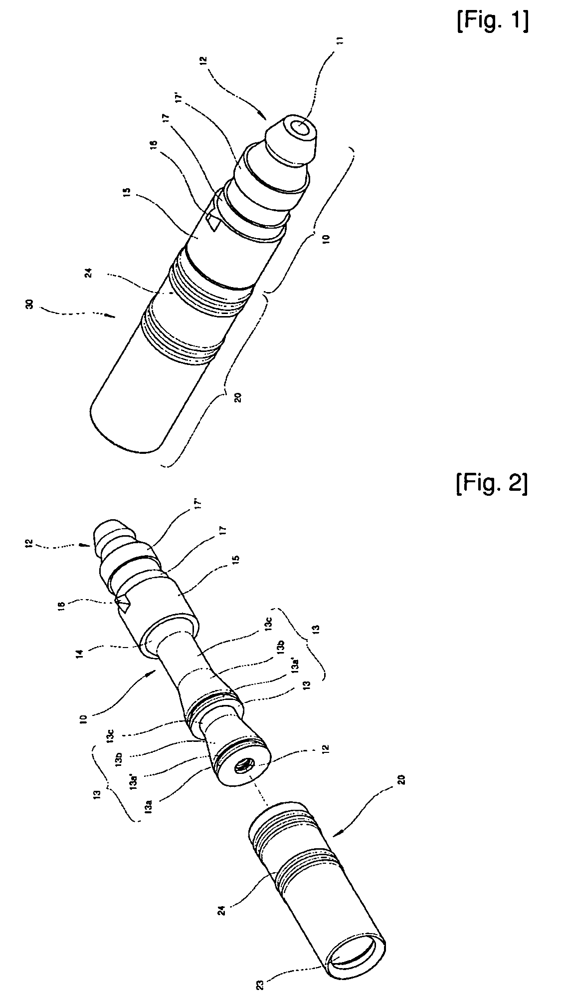
[0020]A packer 30 of the present invention comprises an injection main body 10 and a soft sleeve 20, which are assembled. An inflow route 11 is formed through the injection main body 10 in the longitudinal direction. A nipple part 12 is formed at one end of the injection main body 10, and a plurality of extension units 13, each of which has a trapezoidal section such that its diameter is increased from the front end to the rear end, are consecutively formed at the other end of the injection main body 10. A backward flow prevention groove 11′ having a diameter larger than that of the inflow route 11 is formed in the end of the inflow route 11 opposite to the nipple part 12, and a backward flow prevention unit 17 including a check ball 17a having a spherical shape and a compressed spring 17b, which are sequentially assembled, is formed at the backward flow prevention groove 11′. The soft sleeve 20 has a cylindrical structure having a hollow formed therethrough in the longitudinal dire...

second embodiment

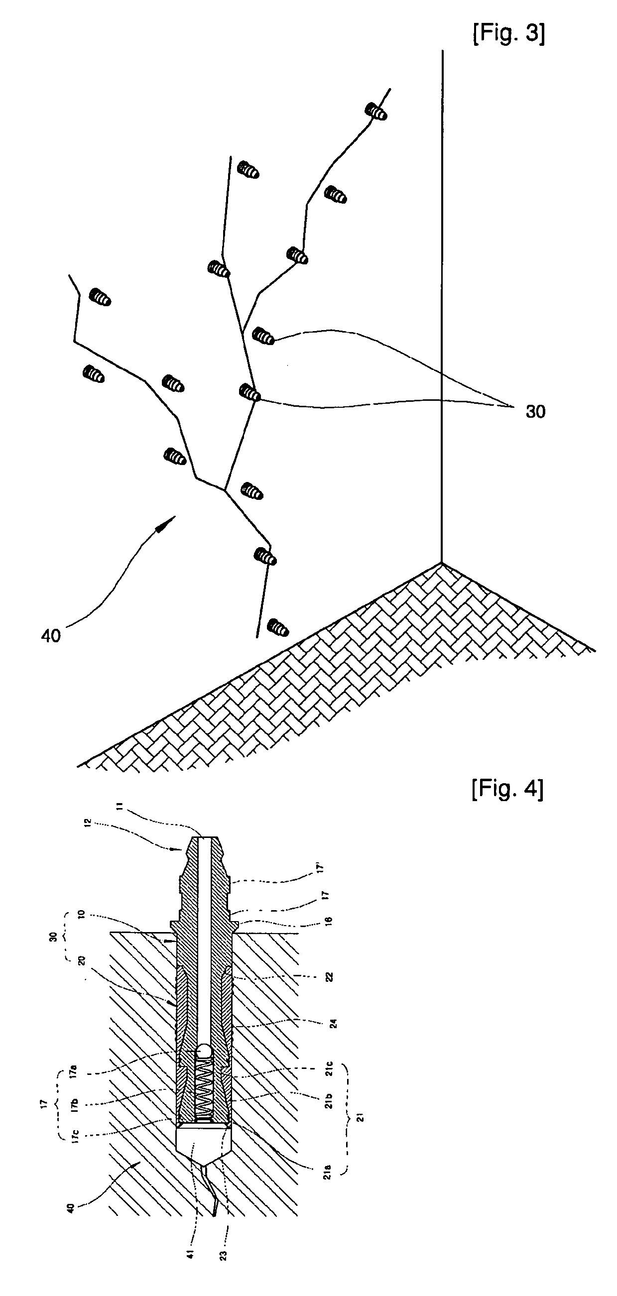
[0032]Hereinafter, with reference to FIGS. 3 to 7, a method for repairing a crack in a concrete body using packers of the present invention will be described.

[0033]In a drilling and blowing step (S1), the fixing holes 41 having a designated depth are formed in the concrete body 40 along a crack using an electric drill, and scraps of foreign substances generated thereby are removed by wind. The fixing holes 41 are formed at an angle of 45 degrees by drilling such that the external surfaces of the fixing holes 41 are spaced from the crack by a designated distance and the internal portions of the fixing holes 41 are connected to the internal portion of the crack. A plurality of the fixing holes 41 are formed along the crack in zigzag.

[0034]Thereafter, in a packer-installing step (S2), as shown in FIGS. 3 and 4, the packer 30 is inserted into each of the fixing holes 41. Here, the soft sleeve 20 is completely inserted into the fixing hole 41, and the injection main body 10 is partially ...


PUM


Abstract

Disclosed is a packer for repairing a crack in a concrete body. The packer includes an injection main body and a soft sleeve. The injection main body includes an inflow route, a nipple part, a plurality of extension units, each of which has a trapezoidal section injection main body, and a backward flow prevention unit in the end of the inflow route opposite to the nipple part. The packer is obtained by assembling the soft sleeve with the extension units of the injection main body, and is installed along the crack of the concrete body, thus easily repairing the crack in the concrete body.

Description

TECHNICAL FIELD[0001]The present invention relates to a packer for repairing a crack in a concrete body, and more particularly to a packer for repairing a crack in a concrete body, which includes an injection main body including an inflow route formed therethrough in the longitudinal direction and a plurality of extension units, each having a trapezoidal section, consecutively formed at one end thereof, and a soft sleeve having a hollow formed therein corresponding to the shapes of the extension units and inserted into one end of the injection main body, in which, when the packer is inserted into the concrete body along the crack and a resin solution is injected into the injection mainbody, the injection main body is partially pushed out under the condition that the soft sleeve maintains its original position, and thus the soft sleeve is uniformly expanded in the circumferential direction, thus preventing the leakage of the resin solution.BACKGROUND ART[0002]Usually, concrete bodies...

Claims


Application Information

Patent Timeline
IPC IPC(8): E04G23/02
CPCE04G23/0203E04G23/0211B05C17/00509
Inventor HWANG, BYEONG KWON
Owner HWANG BYEONG KWON
Why Eureka
Try Eureka