Exhaust Purification Device of an Internal Combustion Engine

Active Publication Date: 2009-04-02
TOYOTA JIDOSHA KK
View PDF11 Cites 49 Cited by
  • Summary
  • Abstract
  • Description
  • Claims
  • Application Information

AI Technical Summary

Benefits of technology

[0006]In the present invention, by producing an extremely reactive intermediate product comprising bonded molecules of an o

Problems solved by technology

However, there is a problem in that, in this internal combustion engine, when making the NOX storage catalyst release NOX by fe

Method used


Image

  • Exhaust Purification Device of an Internal Combustion Engine
  • Exhaust Purification Device of an Internal Combustion Engine
  • Exhaust Purification Device of an Internal Combustion Engine

Examples


Embodiment Construction

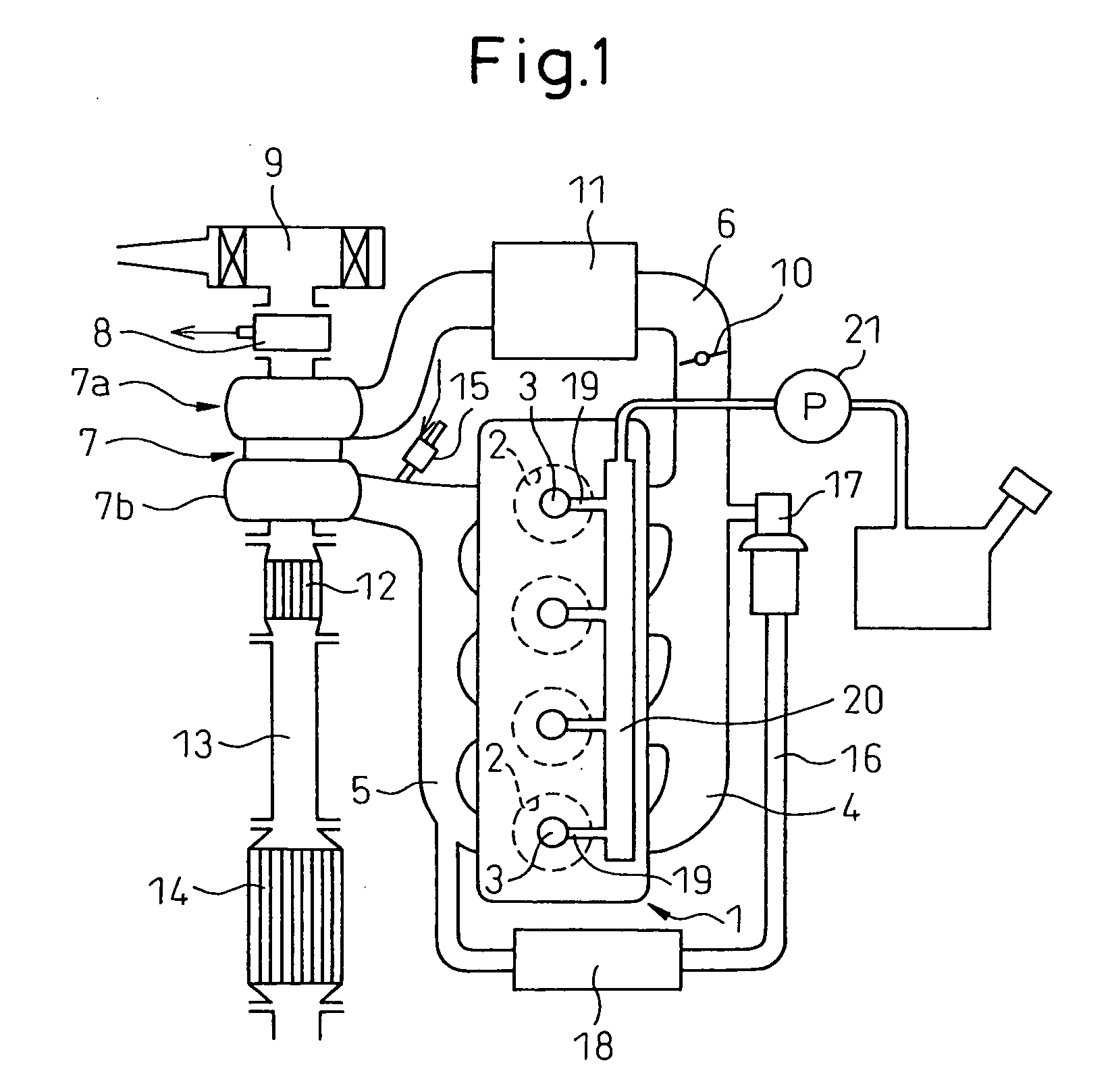
[0012]FIG. 1 shows an overview of a compression ignition type internal combustion engine.

[0013]Referring to FIG. 1, 1 indicates an engine body, 2 a combustion chamber of each cylinder, 3 an electronically controlled fuel injector for injecting fuel into each combustion chamber 2, 4 an intake manifold, and 5 an exhaust manifold. The intake manifold 4 is connected through an intake duct 6 to the outlet of a compressor 7a of an exhaust turbocharger 7, while the inlet of the compressor 7a is connected through an intake air detector 8 detecting an amount of intake air to an air cleaner 9. Inside the intake duct 6, a throttle valve 10 driven by a step motor is arranged. Further, around the intake duct 6, a cooling device 11 for cooling the intake air flowing through the inside of the intake duct 6 is arranged. In the embodiment shown in FIG. 1, the engine cooling water is led into the cooling device 11 where the engine cooling water is used to cool the intake air.

[0014]On the other hand, ...


PUM

PropertyMeasurementUnit
Volumeaaaaaaaaaa
Ratioaaaaaaaaaa

Abstract

In an internal combustion engine, an NOX purification catalyst (14) is arranged in the engine exhaust passage and an intermediate product producing catalyst (12) able to store NOX contained in the exhaust gas is arranged at the upstream of the NOX purification catalyst (14). The intermediate product producing catalyst (12) is fed with mist fuel, and intermediate products (33) comprising bonded molecules comprised of an NOX and hydrocarbon molecules more than an equivalent ratio with respect to an NOX molecule are produced from the NOX trapped in the intermediate product producing catalyst (12) or the NOX contained in the exhaust gas and the fed fuel.

Description

TECHNICAL FIELD[0001]The present invention relates to an exhaust purification device of an internal combustion engine.BACKGROUND ART[0002]Known in the art is an internal combustion engine arranging in the engine exhaust passage an NOX storage catalyst which stores NOX contained in the exhaust gas when the air fuel ratio of the inflowing exhaust gas is lean and releases the stored NOX when the air fuel ratio of the inflowing exhaust gas is a stoichiometric air fuel ratio or rich and arranging a compact three-way catalyst in the engine exhaust passage upstream of this NOX storage catalyst (see for example Japanese Patent Publication (A) No. 2004-108176). In this internal combustion engine, if the NOX storage ability of the NOX storage catalyst approaches saturation, the air fuel ratio of the exhaust gas is temporarily made rich whereby NOX is released from the NOX storage catalyst and reduced.[0003]However, there is a problem in that, in this internal combustion engine, when making th...

Claims


Application Information

Patent Timeline
IPC IPC(8): F01N3/20
CPCB01D53/9431F01N13/0093B01D2251/208B01D2255/1021B01D2255/2042B01D2255/91B01D2255/9202B01D2257/404B01D2258/012F01N3/0814F01N3/0835F01N3/0842F01N2240/30F01N2250/12F01N2340/00F01N2610/03F01N2610/102Y02T10/24B01D53/9477B01D53/9413B01D2255/9022F01N3/0807F01N2570/14Y02T10/12Y02A50/20B01D53/94F01N3/08F01N3/24
Inventor TSUJIMOTO, KENICHIINOUE, MIKIOHIROTA, SHINYA
Owner TOYOTA JIDOSHA KK
Why Eureka
Try Eureka