

Tactical truck system dashboard
a truck system and dashboard technology, applied in the field of vehicles, can solve the problems of presenting certain difficulties, and affecting the performance of the dashboard, and achieve the effect of reducing the workload and/or better accommodating the driver and passenger interfa
- Summary
- Abstract
- Description
- Claims
- Application Information
AI Technical Summary
Benefits of technology
Problems solved by technology
Method used
Image

Examples
first embodiment
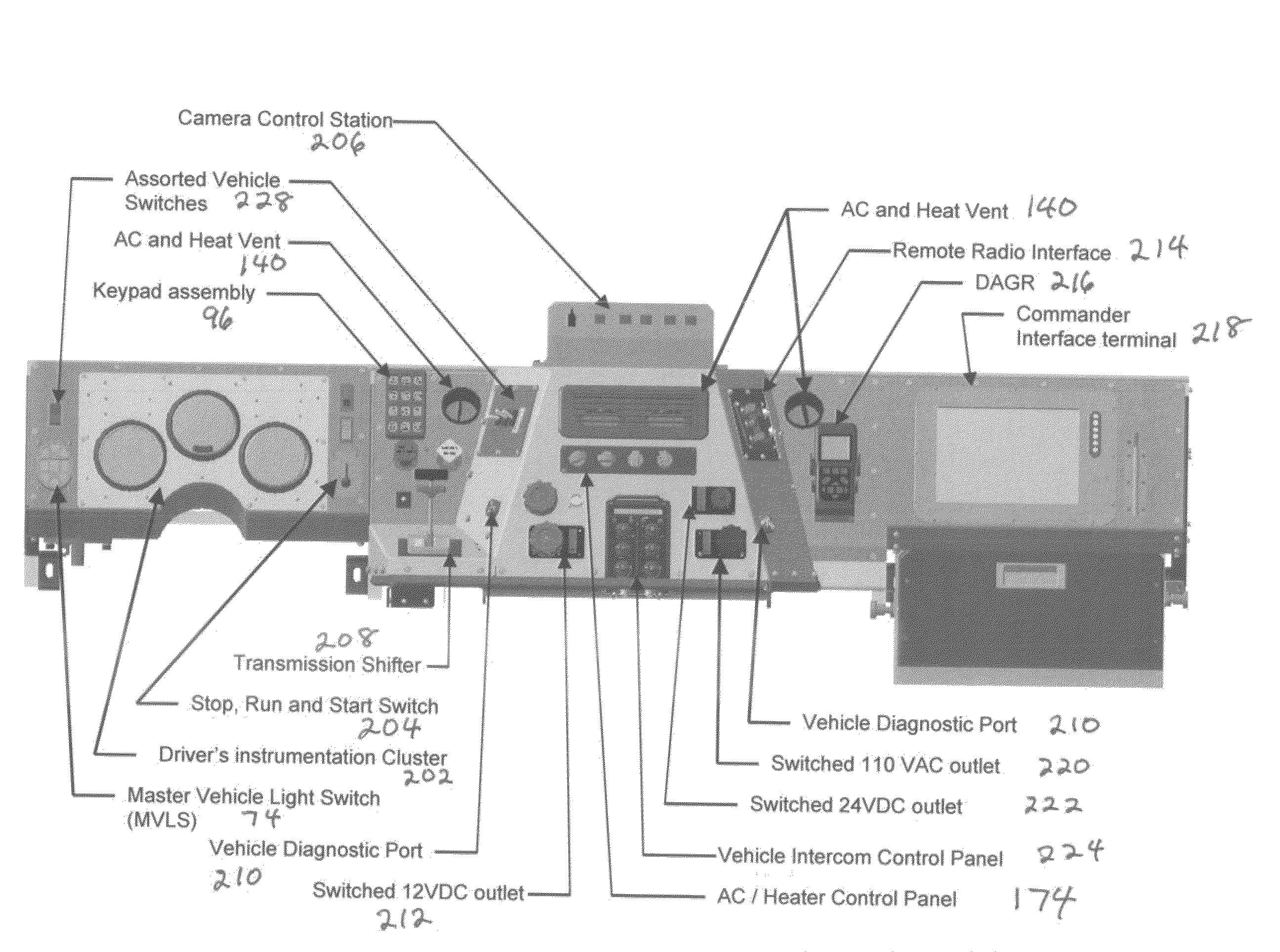
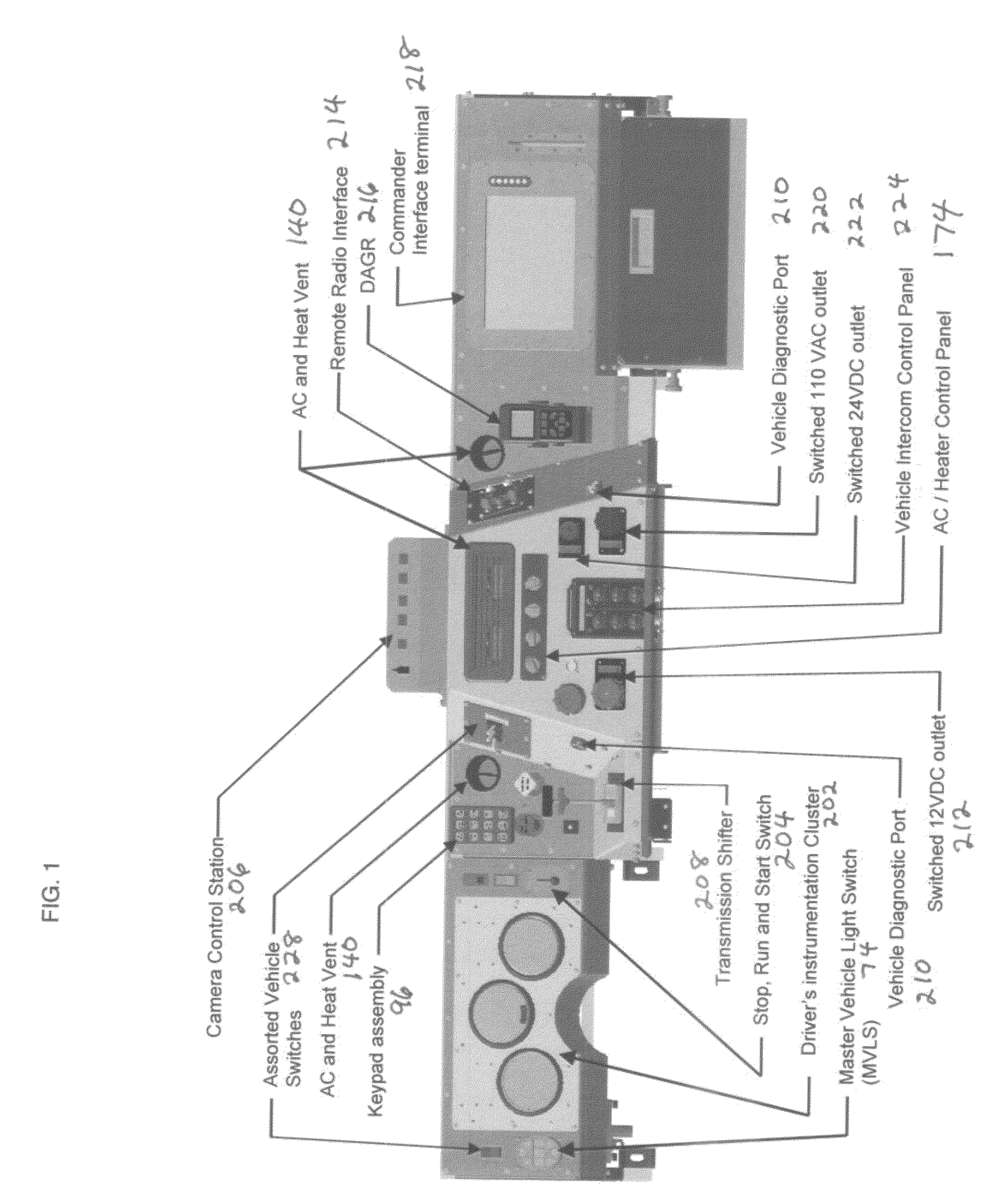
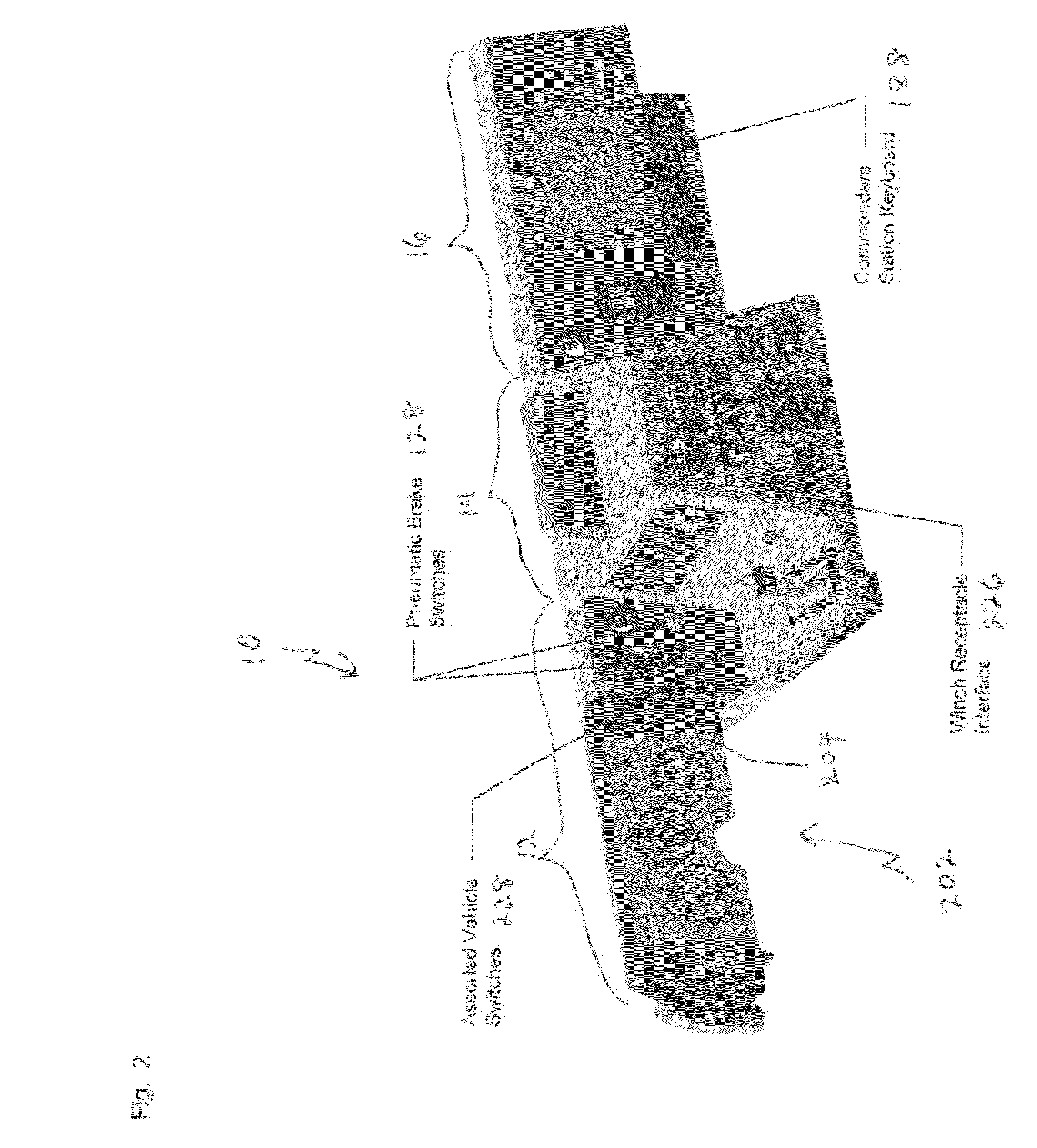
[0072]FIGS. 1 and 2 show such a dashboard 10 which includes a driver section 12, a middle section 14, and a command section 16.
[0073]FIGS. 1, 2 and 7 show the driver's instrumentation cluster 202, a stop, run and start switch 204, a keypad assembly 96, AC and heat air vents 140, master vehicle light switch 74, camera control station 206, a transmission shifter 208, vehicle diagnostic port 210, switched 12V DC outlet 212, AC and heat vent 140, remote radio interface 214, DAGR 216, commander interface terminal 218, switched 110v AC outlet 220, switched 24v DC outlet 222, vehicle intercom control panel 224, AC / Heater control panel or cab climate control panel 174, brake switches 128 (which can be pneumatic), a keyboard 188 for the commander interface terminal 218, winch receptacle interface 226, and assorted vehicle switches 228.
[0074]FIG. 7 is a side view of the first embodiment shown in FIGS. 1 and 2 which shows a driver 258 seated and the pedals 248 mounted to the dashboard 10, as w...
second embodiment
[0075]FIGS. 3, 4 and 8 show such a dashboard 10 which includes a driver section 12, a middle section 14, and a command section 16.
[0076]These figures show the driver's instrumentation cluster 202, a stop, run and start switch 204, a camera control station 206, a keypad assembly 96, master vehicle light switch 74, a transmission shifter 208, vehicle diagnostic port 210, switched 12V DC outlet 212, AC and heat vent 140, commander interface terminal or operational display unit 218, auxiliary display unit (ADU) 230, switched 110v AC outlet 220, switched 24v DC outlet 222, vehicle intercom control panel 224, brake switches 128 (which can be pneumatic), a keyboard 188 for the operational display unit 218 and / or for the auxiliary display unit 230, winch receptacle interface 226, assorted vehicle switches 228, and assorted radios 232.
[0077]FIG. 8 is a side view of the second embodiment shown in FIGS. 3 and 4 which shows the cab without a driver and the pedals 248 mounted to the dashboard 10...
third embodiment
[0078]FIGS. 5, 6 and 9 show such a dashboard 10 which includes a driver section 12, a middle section 14 and a command section 16.
[0079]These figures show the driver's instrumentation cluster 202, a stop, run and start switch 204, a keypad assembly 96, a master vehicle light switch 74, a transmission shifter 208, a vehicle diagnostic port 210, commander interface terminal or operational display unit 218, an auxiliary display unit (ADU) 230, a keyboard 188 for the operational display unit 28 and / or for the auxiliary display unit 230, vehicle intercom control panel 224, a keyboard receptacle 236, intercom receptacles 238, assorted radios 232, switched 12v DC outlets 212, switched 24v DC outlets 222, switched 110v AC outlets 220, an HVAC unit 234, distributive power modules 240, trailer brake controller 242, computer module (NCS) 244, brake switches 128 (which can be pneumatic), winch receptacle interface 226, and assorted vehicle switches 228 and main disconnect switch 246.
[0080]FIG. 9...
PUM
 Abstract
Description
Claims
Application Information