Constant current source circuit
a source circuit and constant current technology, applied in the direction of electric variable regulation, process and machine control, instruments, etc., can solve the problems of reducing the threshold voltage vt, the output resistance rsub>out /sub>cannot be increased to be higher, and the difficulty of engineers to determine the lower limit of operation voltage of analog circuits, etc., to reduce the influence of output voltage and reduce the variation of output current
- Summary
- Abstract
- Description
- Claims
- Application Information
AI Technical Summary
Benefits of technology
Problems solved by technology
Method used
Image
Examples
first embodiment
1. First Embodiment
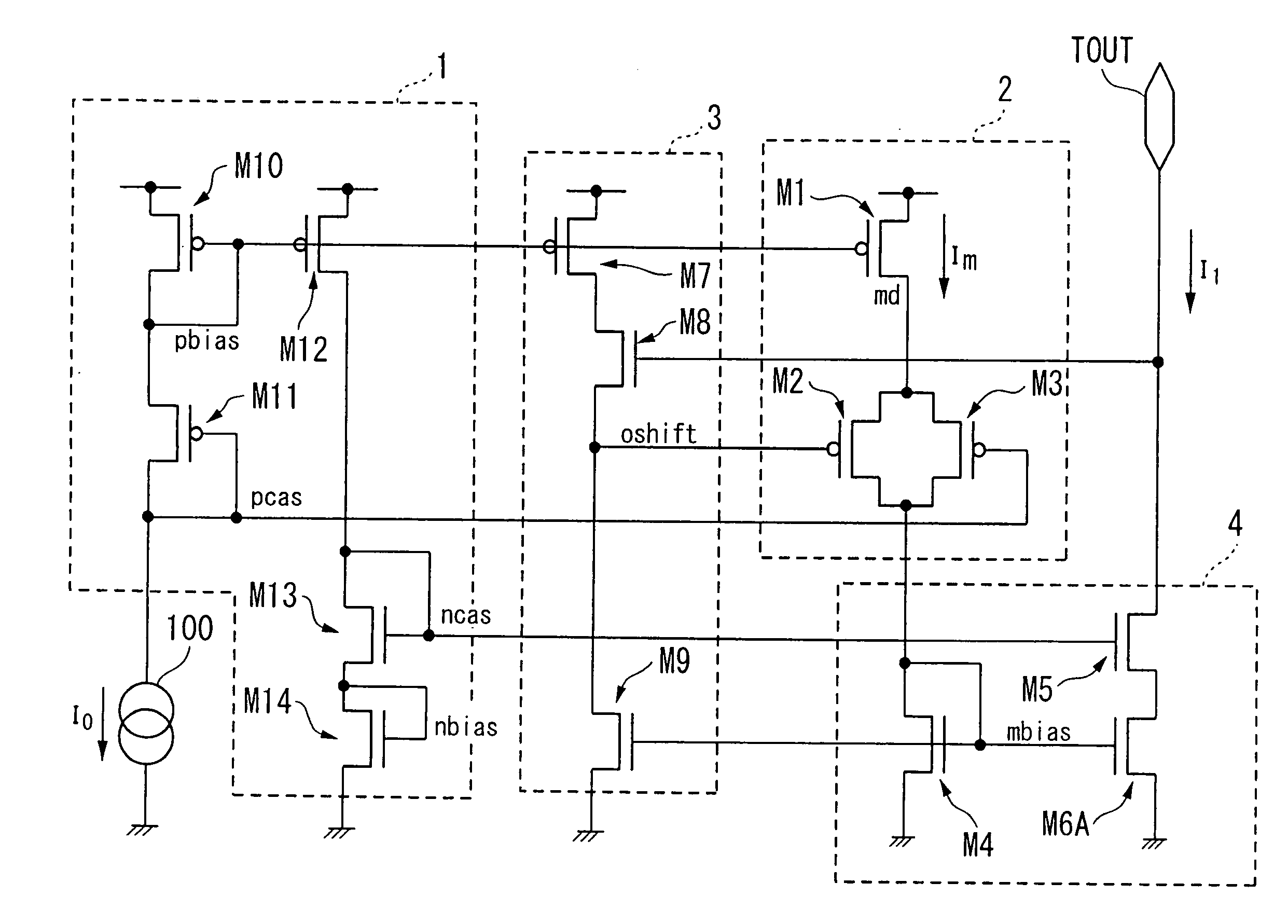
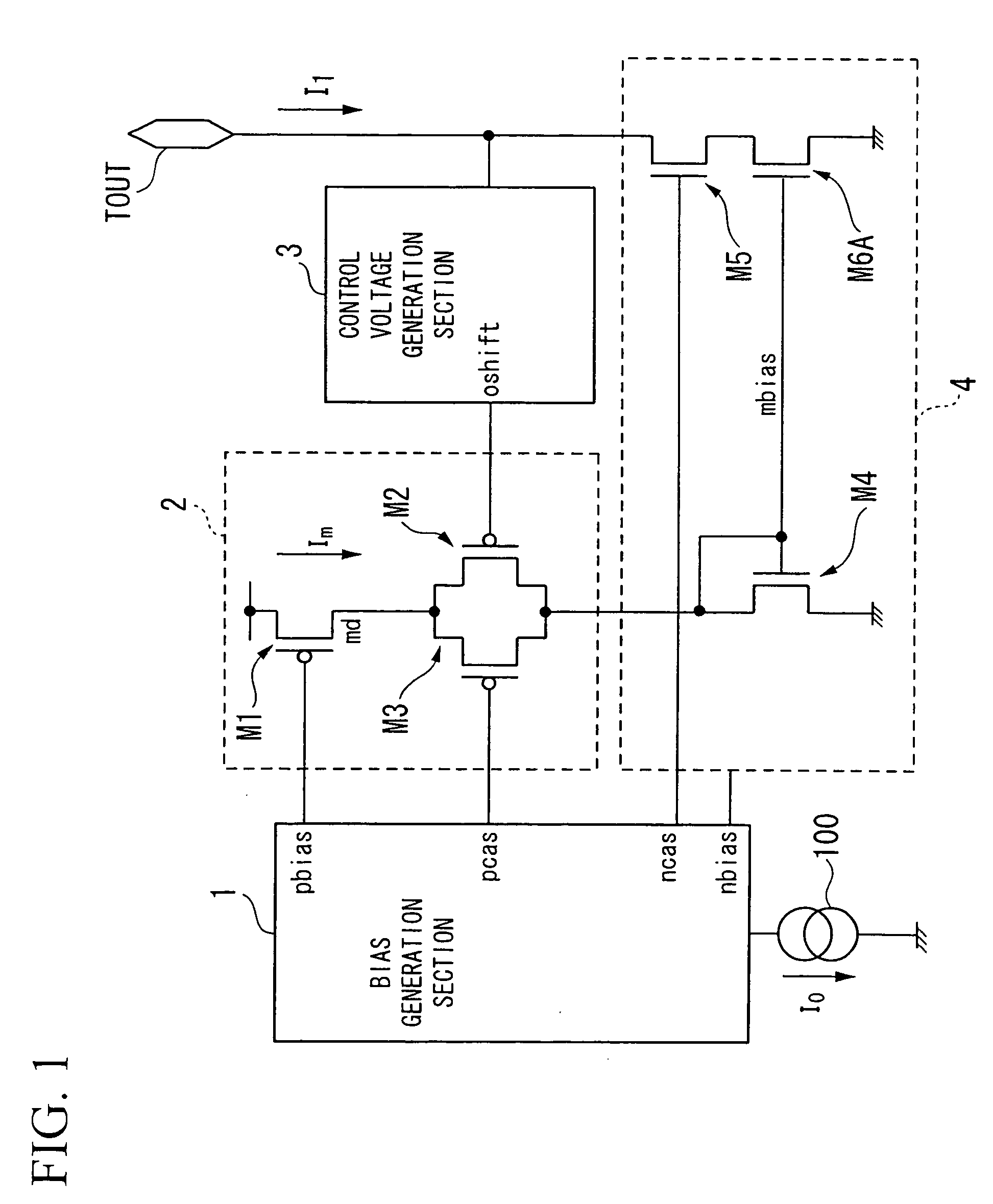
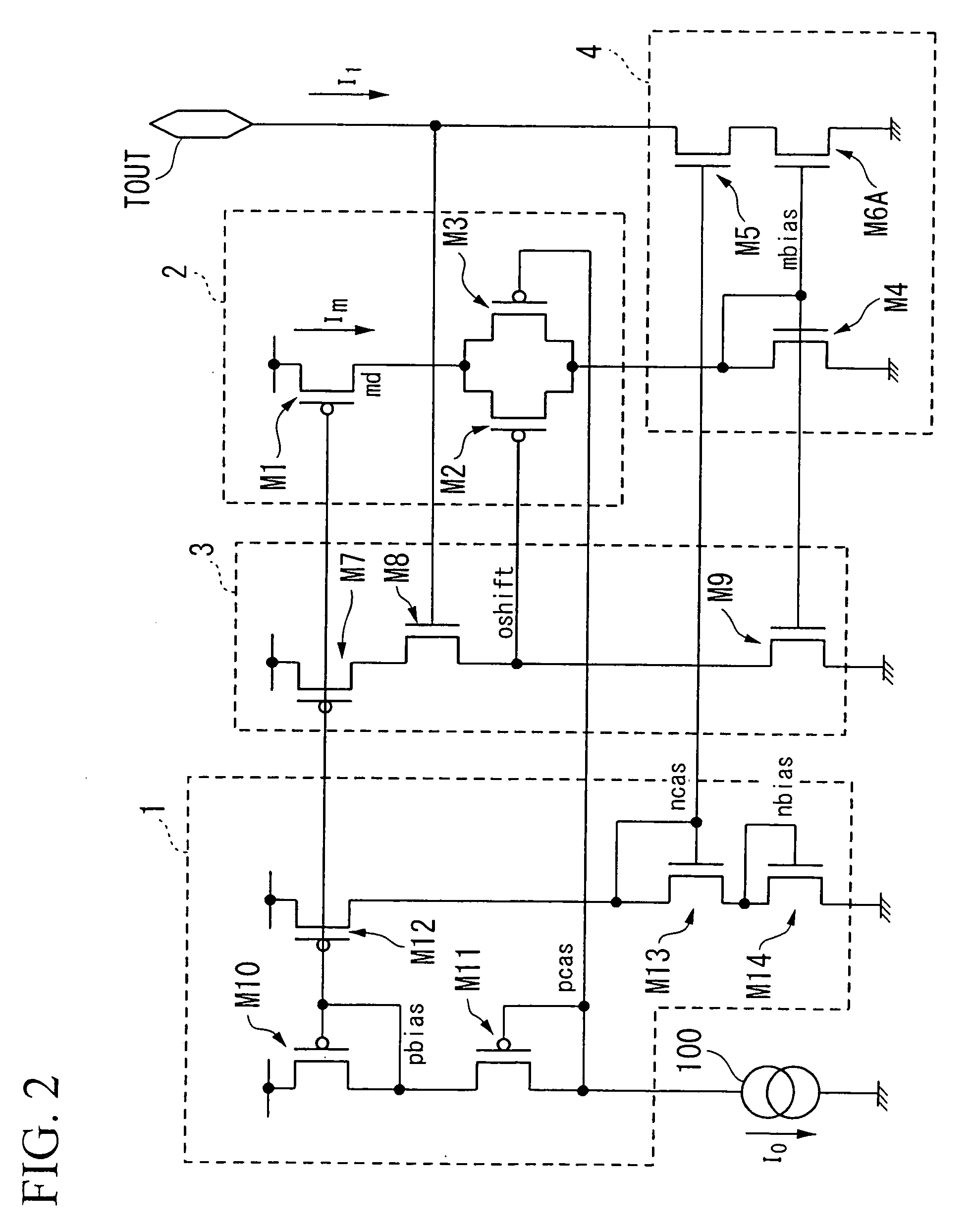
[0064]Referring now to FIG. 1, a constant current source circuit according to a first embodiment of the present invention includes a bias generation section 1, a reference current adjustment section 2, a control voltage generation section 3, and a current mirror section 4.
[0065]Based on a reference current I0 caused by a constant current source 100, the bias generation section 1 generates a first bias voltage pbias and a second bias voltage pcas for use in the reference current adjustment section 2 as well as a third bias voltage ncas for use in the current mirror section 4.
[0066]The output voltage of an output terminal TOUT is applied to the control voltage generation section 3. The control voltage generation section 3 generates a control voltage oshift, which is produced by shifting a prescribed voltage from the output voltage. It outputs the control voltage oshift to the reference current adjustment section 2.
[0067]The reference current adjustment section 2 is ...
second embodiment
2. Second Embodiment
[0104]Next, a constant current source circuit according to a second embodiment of the present invention will be described with reference to FIGS. 4 and 5. FIG. 5 is a circuit diagram showing the constitution of the constant current source circuit of the second embodiment.
[0105]Similar to the first embodiment, the constant current source circuit of the second embodiment is constituted of the bias generation section 1, the reference current adjustment section 2, the control voltage generation section 3, and the current mirror section 4.
[0106]In FIG. 5, parts identical to those of the first embodiment shown in FIG. 2 are designated by the same reference numerals; hence, only differences in the constitution and operation will be described with respect to the second embodiment.
[0107]Based on the reference current I0 created by the constant current source 100, the bias generation section 1 generates and outputs the first bias voltage pbias and the second bias voltage p...
third embodiment
3. Third Embodiment
[0115]Next, a constant current source circuit according to a third embodiment of the present invention will be described with reference to FIGS. 6 to 8. FIG. 6 is a circuit diagram showing the constitution of the constant current source circuit of the third embodiment. The third embodiment is designed to apply the reference current adjustment section 2 of the first embodiment to the low-voltage cascode current mirror circuit shown in FIG. 16.
[0116]The constant current source circuit of the third embodiment does not include the control voltage generation section 3 used in the first embodiment and is thus constituted of the bias generation section 1, the reference current adjustment section 2, and the current mirror section 4.
[0117]In FIG. 6, parts identical to those of the second embodiment shown in FIG. 5 are designated by the same reference numerals; hence, only differences in the constitution and operation will be described with reference to the third embodiment...
PUM
 Abstract
Description
Claims
Application Information
 - R&D
- Intellectual Property
- Life Sciences
- Materials
- Tech Scout
- Unparalleled Data Quality
- Higher Quality Content
- 60% Fewer Hallucinations
Browse by: Latest US Patents, China's latest patents, Technical Efficacy Thesaurus, Application Domain, Technology Topic, Popular Technical Reports.
© 2025 PatSnap. All rights reserved.Legal|Privacy policy|Modern Slavery Act Transparency Statement|Sitemap|About US| Contact US: help@patsnap.com


