Digital blink comparator apparatus and software and methods for operation

Inactive Publication Date: 2009-04-02
KUHN MATTHEW JOSEPH
View PDF5 Cites 13 Cited by
  • Summary
  • Abstract
  • Description
  • Claims
  • Application Information

AI Technical Summary

Benefits of technology

[0022]It is also an object of this invention to provide medical imaging systems utilizing as an element thereof more or less conventional medical imaging technology, in combination with a novel software adaptation of commercially-available software, which allows a series of two or more digital images of a particular three-dimensional body part or region to be alternatively displayed, one image substantially upon the other, and / or aligned with one another, in a rapid fashion, thereby presenting the alternating images to the interpreter / diagnostician in a fashion such that the images rapidly alternate back and forth causing a visually perceptible “blink” effect to identify changes or differences in the images being compared.
[0033]Still another image manipulation technique is to optionally digitally rotate one or both images so that they align better if the patient is turned or leaning when one of the images is taken. An additional optional technique to improve the capability of the digital blink comparator apparatus and methods of this invention is to utilize or adapt software so as to superimpose the two images at the same time on the display screen in a semi-transparent manner so that alignments of the two images in all directions can more easily be accomplished. These operations will be recognized by those skilled in the art as familiar computer image manipulation processes, and most, if not all, modem computer operating systems / software applications have, or can be adapted to have, such image manipulation capabilities based on the teachings of this invention.

Problems solved by technology

At the present time, commercially-available digital imaging software does not provide for viewing or generating comparison studies in a mode of rapidly alternating two or more images at substantially the same display position on a single monitor or other viewing device.

Method used


Image

  • Digital blink comparator apparatus and software and methods for operation
  • Digital blink comparator apparatus and software and methods for operation
  • Digital blink comparator apparatus and software and methods for operation

Examples


Embodiment Construction

and the accompanying drawings.

BRIEF DESCRIPTION OF THE DRAWINGS

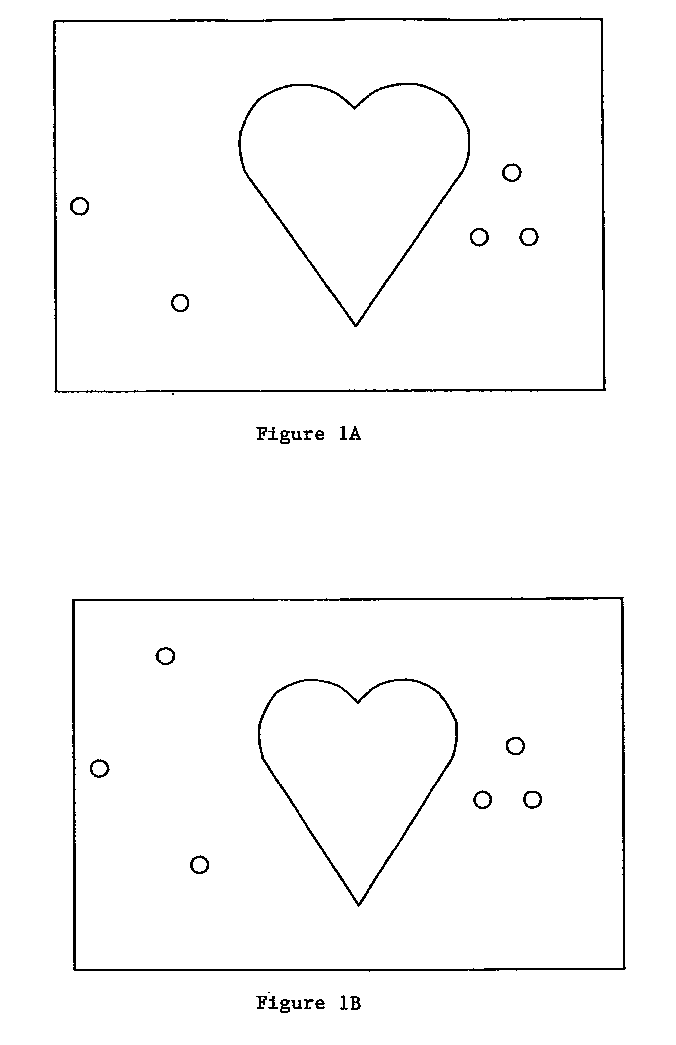
[0036]FIGS. 1A and 1B schematically show two hypothetical frontal chest radiographic views taken at different times.

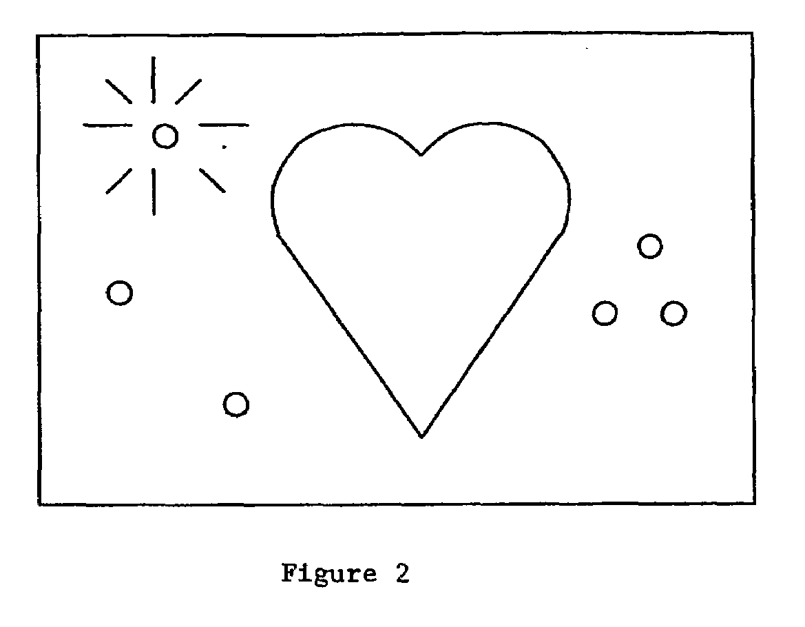
[0037]FIG. 2 is a schematic representation of superimposing the images of FIGS. 1A and 1B.

[0038]FIGS. 3A and 3B are schematic representations of a comparison of two MRI image studies using a manual “hanging” comparison method.

[0039]FIG. 4 illustrates a typical “hanging” protocol for MRI image interpretation using a computerized display and storage system.

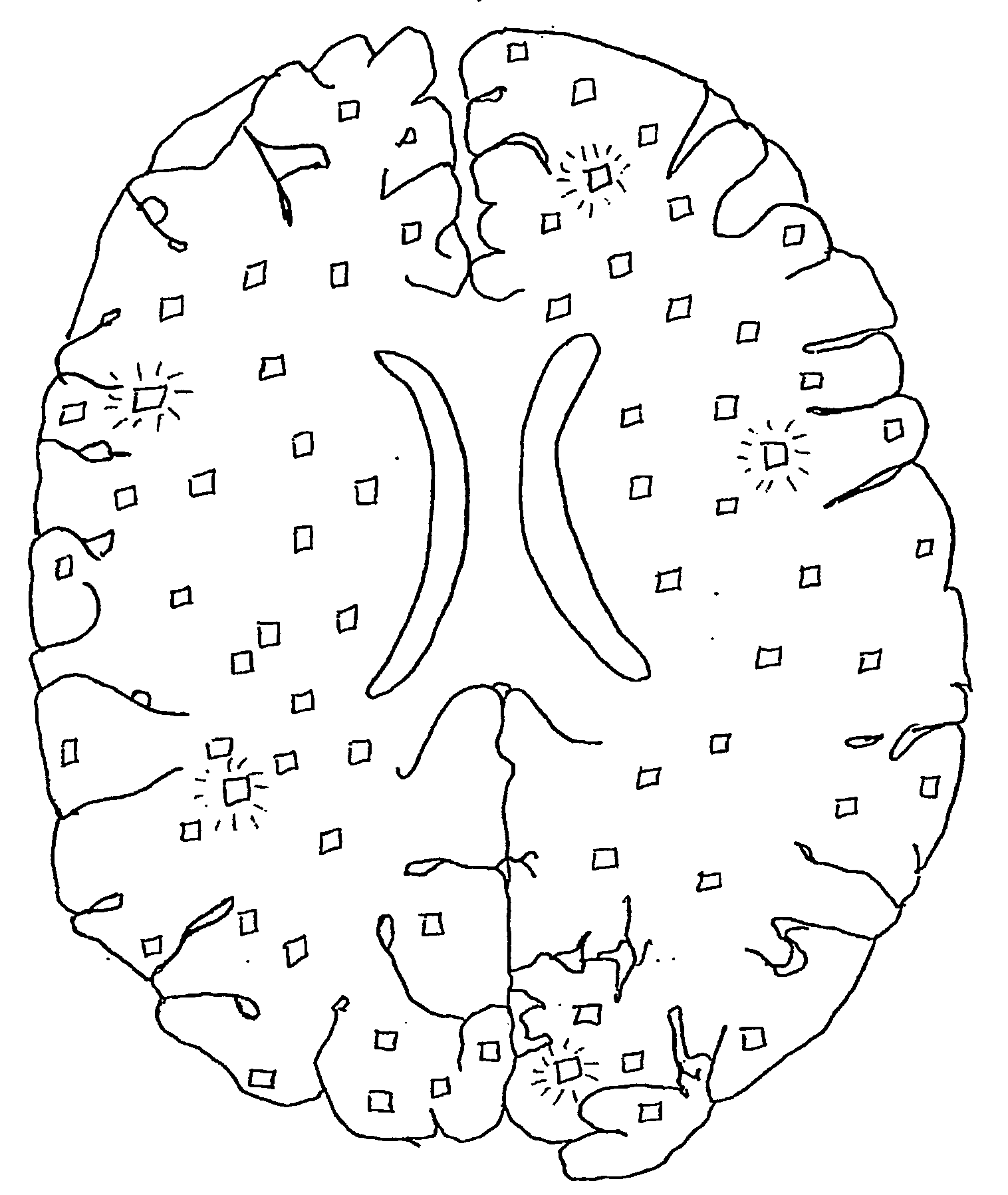
[0040]FIGS. 5A and 5B schematically represent CT or MRI images of a brain section taken at different times.

[0041]FIGS. 6A and 6B show the FIG. 5A and FIG. 5B images, respectively, with the FIG. 5B image realigned and re-scaled in accordance with embodiments of this invention in preparation for applying the blink comparator technique of this invention.

[0042]FIG. 7 shows a schematic representation of an image produced by applying a digital blink comparator me...


PUM


Abstract

New techniques, imaging software, and related imaging systems for visualizing and comparing medical images are disclosed. The apparatus of this invention generally comprises a digital imaging system including a visual display device in combination with software adapted so as to enable two or more digital images to be rapidly alternately superimposed on the same display space and displayed to a viewer (FIG. 7). The digital blink comparator apparatus and methods of this invention may be carried out using or be applied to a wide variety of existing medical imaging interpretation devices including, but not limited to, standard PACS, web-based PACS, cardiac imaging, ophthalmologic imaging, and dental imaging.

Description

FIELD OF THE INVENTION[0001]This invention relates generally to the field of medical imaging technology, more specifically to radiology and related applications, wherein images of a portion of a body, e.g., images produced by X-rays, CAT scans, MRI techniques, and the like, are used for diagnosis, evaluation, or other medical purposes. More particularly, this invention relates to a digital “blink” method of alternately and in rapid succession displaying new and old images, which have been sized and oriented such that the alternately displayed images are superimposed in substantially the same display location, to more readily detect changes in size and number of abnormalities.[0002]The techniques of this invention provide greater accuracy and time efficiencies than are possible to achieve with prior art approaches. Currently, radiologists have no real notion as to when they have completed the time-consuming process of looking for changes or differences in multiple medical images duri...

Claims


Application Information

Patent Timeline
IPC IPC(8): G06K9/00A61B5/00
CPCA61B5/00A61B5/4547A61B8/463A61B6/463A61B8/00A61B6/00
Inventor KUHN, MATTHEW JOSEPH
Owner KUHN MATTHEW JOSEPH
Why Eureka
Try Eureka