
Focal point detection device and image capture device

a detection device and focal position technology, applied in the direction of printers, cameras, instruments, etc., can solve the problem of not being able to detect the focal position, and achieve the effect of good focal position detection and good image captur

Inactive Publication Date: 2009-04-02
FUJIFILM CORP
View PDF7 Cites 6 Cited by
  • Summary
  • Abstract
  • Description
  • Claims
  • Application Information

AI Technical Summary

Benefits of technology

The present invention provides a focal point detection device and image capture device that can detect the focal position even when the focus lens is displaced due to an impact. The device includes an optical system with a focus lens, a drive unit that moves the focus lens, a computing unit that computes a focus control evaluation value, and a controller that controls the computing unit to compute the evaluation value while moving the focus lens in a predetermined range. An impact detection sensor can also be added to determine if impact has occurred and improve accuracy in detecting the focus lens displacement. The invention is particularly useful for bent optical systems and can ensure good image capture even when the focus lens is displaced due to an impact.

Problems solved by technology

However, when such a bent optical system is adopted, if an impact occurs during image capture, position of the carriage may be displaced downward (jumping teeth) due to the weight of the focus lens itself, resulting in the focal position not being possible to detect, namely, being outside of the detection range of focal position.

Method used


Image

  • Focal point detection device and image capture device
  • Focal point detection device and image capture device
  • Focal point detection device and image capture device

Examples


Embodiment Construction

[0031]Explanation is given below of details of the preferable mode of working the present invention, with reference to the figures.

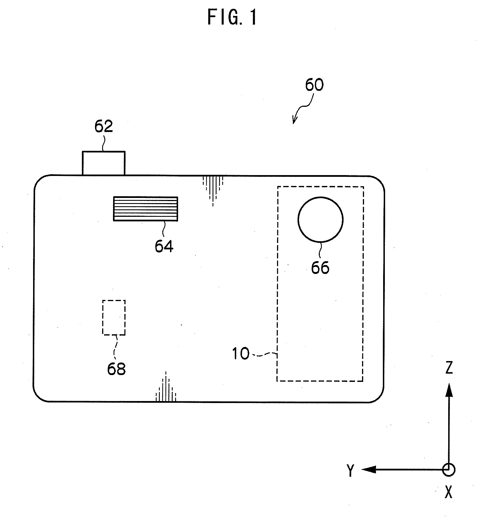
[0032]A front view of a digital camera 60 according to the present invention is shown in FIG. 1. Disposed on the top and front faces of the digital camera 60 are a shutter button 62 for instructing image capture, a flash unit 64 for carrying out flash exposure to a photographic subject, and a lens aperture portion 66 through which light from the photographic subject is incident. An angular velocity sensor 68 that detects camera shake for carrying out correction therefor, an optical system unit 10 accommodating a zoom lens, a focus lens etc., and also electrical circuits and the like are built into the digital camera 60.

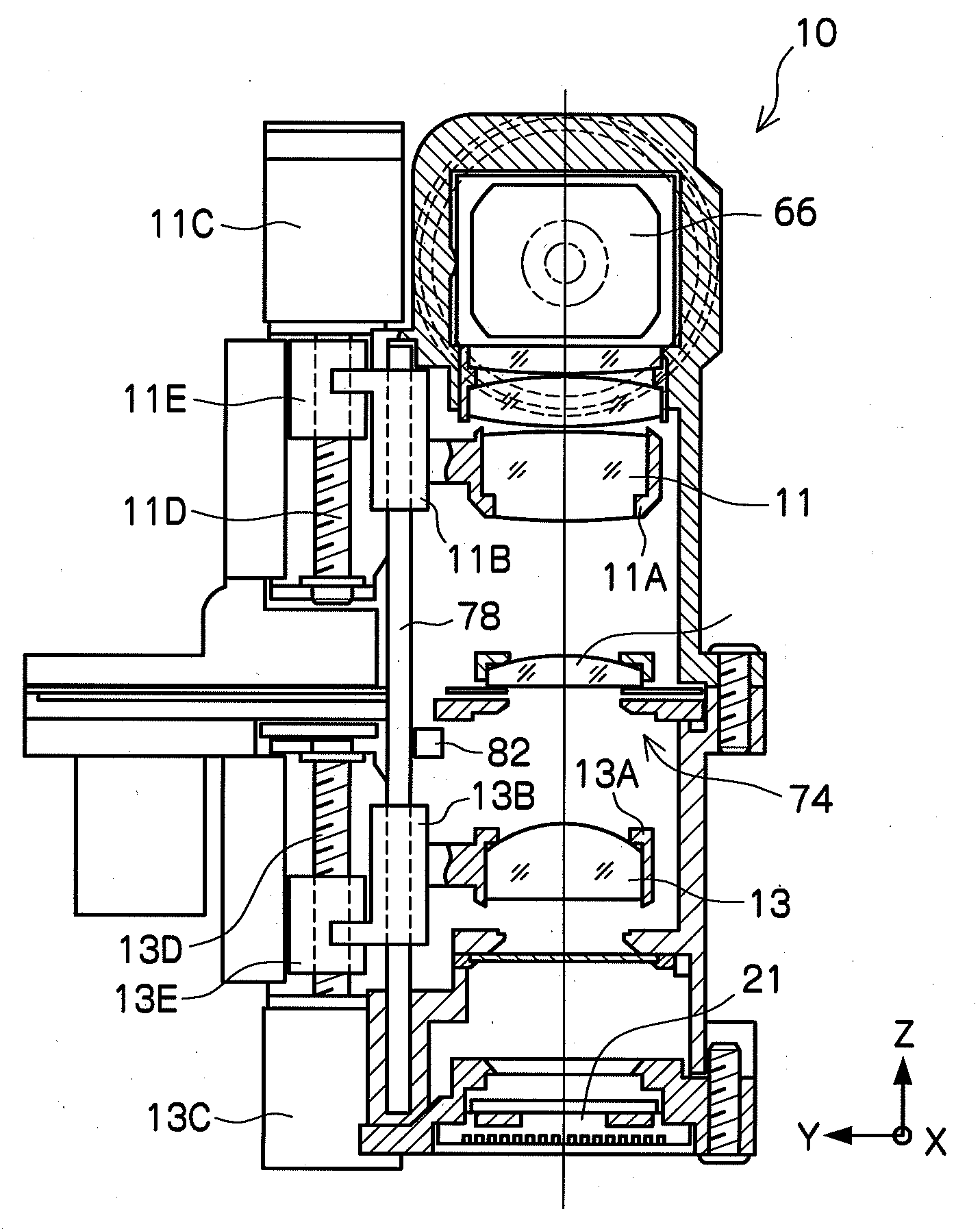
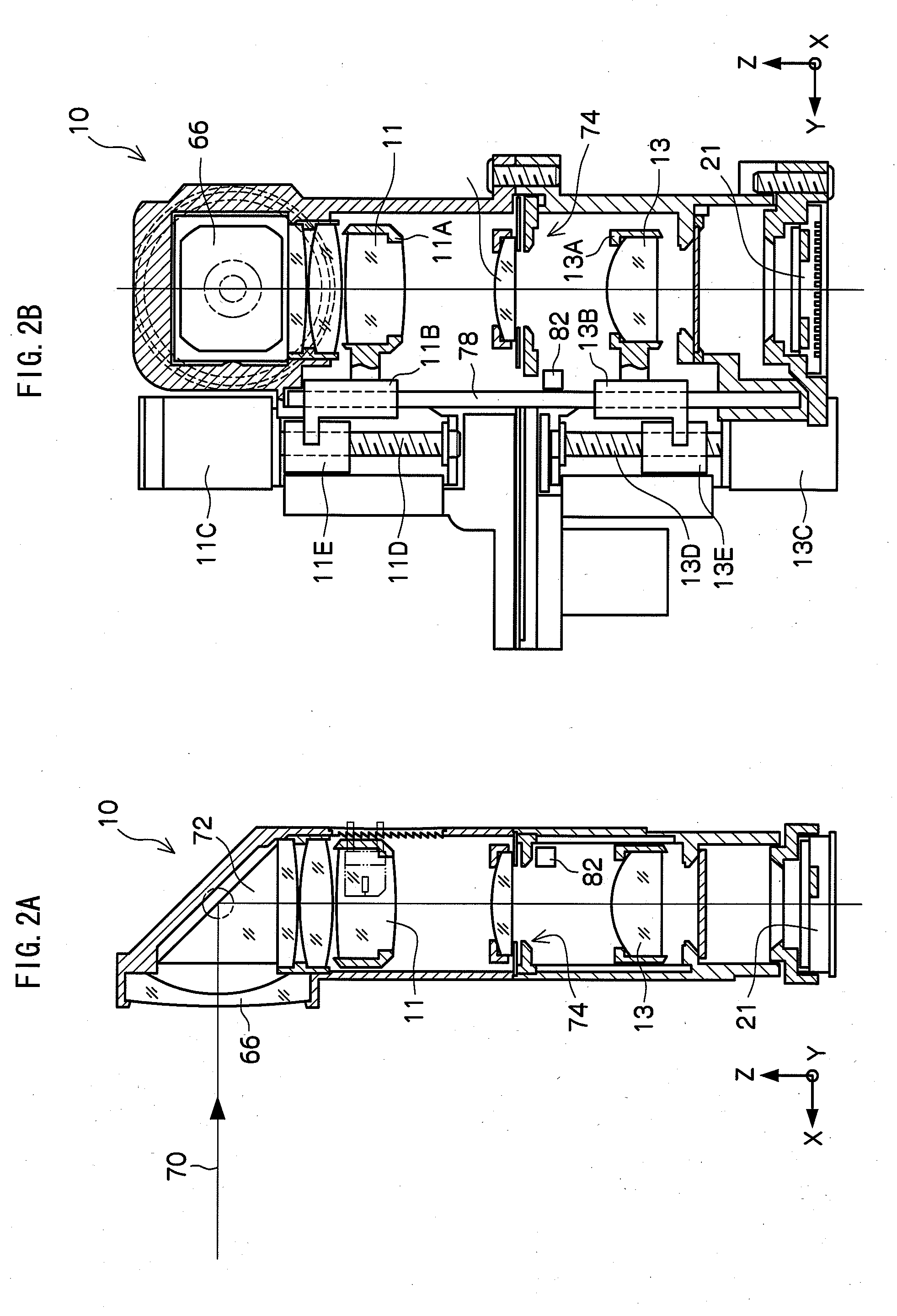
[0033]Details of the configuration of the optical system unit 10 are shown in FIGS. 2A and 2B, with FIG. 2A being a side view of the optical system unit 10 and FIG. 2B being a front view.

[0034]As shown in FIG. 2A, the optical system unit 1...


PUM


Abstract

A focal point detection device capable of good focal position detection even when the focus lens is displaced due to impact, and an image capture device. During focal point detection, when focal point detection is impossible, whether AF evaluation values decrease continuously is determined, and whether impact has occurred is detected when decreasing continuously. The focus lens is moved to the initial position when AF evaluation values decrease continuously and impact is detected, as the focus lens is possibly displaced. After the focal point detection is performed again and it is determined whether it is possible to detect the focal point, the focus lens is moved to the focal position when focal point detection is possible, and the focus lens is moved toward the nearside when focal point detection is not possible, on the basis that the photographic subject has been image captured outside of the set image capture range.

Description

CROSS-REFERENCE TO RELATED APPLICATION[0001]This application claims priority under 35 USC 119 from Japanese Patent Application No. 2007-242791, the disclosure of which is incorporated by reference herein.BACKGROUND OF THE INVENTION[0002]1. Field of the Invention[0003]The present invention relates to a focal point detection device and to an image capture device, and in particular to a focal point detection device that carries out automatic focal point detection and is installed in an image capture device such as a camera, and such an image capture device.[0004]2. Description of the Related Art[0005]Various devices have been proposed which incorporate “autofocus” functions for automatically detecting the focal position of the lens of an image capture device such as a camera. Technology has, for example, been disclosed in Japanese Patent Application Laid-Open (JP-A) No. 1-187516 for driving the lens to the initial rest position when determination is made that focusing is not possible.[...

Claims


Application Information

Patent Timeline
Patent Type & Authority Applications(United States)
IPC IPC(8): G03B17/00G03B13/36
CPCG02B5/04G02B7/102H04N5/23212G03B13/36G03B17/17G02B15/177G02B15/146H04N23/55H04N23/673
Inventor NAKAZAWA, MICHITAKAMAEJIMA, AKIHIROICHIKAWA, SHIGERU
Owner FUJIFILM CORP
Learn More