

Perfusion System for Pancreas Treatment
a technology of pancreas and perfusion system, which is applied in the field of perfusion system, can solve the problems of difficult surgical intervention for pancreatic cancer, difficult early detection of pancreatic cancer, and may be too late to detect, so as to achieve the effect of suppressing the broth
- Summary
- Abstract
- Description
- Claims
- Application Information
AI Technical Summary
Benefits of technology
Problems solved by technology
Method used
Image

Examples
embodiment 1
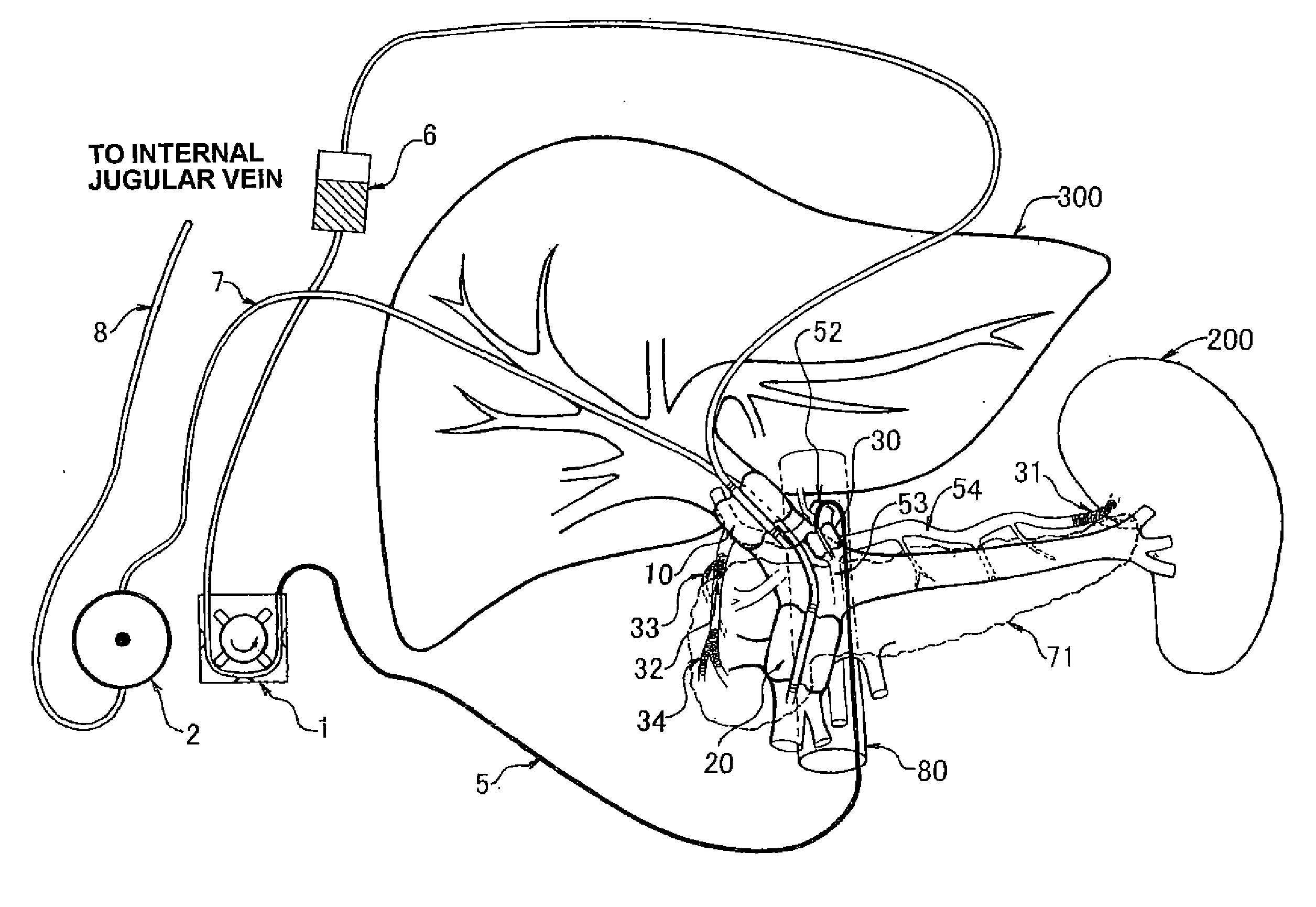
[0043]FIG. 6 shows one exemplary structure of the perfusion system for the patient having the most general structure in which the dorsal pancreatic artery 53 branches from the splenic artery 54 as shown in FIG. 3A (a). In the embodiment of FIG. 6, for straightforward understanding of the perfusion system for pancreas treatment, the venous system shown in FIG. 4 and the arterial system shown in FIG. 5 are superposed visually. In FIG. 6, components 1 and 2 are perfusion pumps, and the component 6 is a reservoir for injecting the pharmaceutical such as anticancer agent. The indwelling method for the balloon catheters 10 and 20 in the venous system and the indwelling method for the balloon catheter 30 in the arterial system are as described in FIG. 4 and FIG. 5, respectively. In the subsequent embodiments, note that 10 Fr catheter is used for the balloon catheter 10 and 12 Fr catheter is used for the balloon catheters 20 and 30.
[0044]The venous blood inside the enclosed area may be suck...
embodiment 2
[0046]Next, refer to FIG. 7. FIG. 7 shows a method for forming the enclosed area in the arterial system in case that the dorsal pancreatic artery branches from the celiac artery trunk as shown in FIG. 3A (b). In this case, the occlusion position by using coils is the same as the case shown in FIG. 6, but a couple of balloon catheters 30 and 40 are used. At first, in similar matter to FIG. 6, the splenic artery 54 may be occluded by the coil 31. Next, the anterior superior pancreaticoduodenal artery 60 and the right gastro-omental artery 61 may be occluded by the coil 34. Next, the posterior superior pancreaticoduodenal artery 59 and the gastroduodenal artery 58 may be occluded by the coils 33 and 32, respectively. After completing the occlusion operation by way of coils, the balloon catheter 40 may be inserted through the aorta 80 and the coeliac artery 52 into the common hepatic artery 56 at first, and then inflated and indwelled there. Finally, the balloon catheter 30 may be inser...
embodiment 3
[0048]Next, refer to FIG. 8. FIG. 8 shows a method for forming the enclosed area in the arterial system in case that the dorsal pancreatic artery branches from the common hepatic artery as shown in FIG. 3A (c). In this case, the occlusion position by using coils is the same as the case shown in FIG. 6. This embodiment using a couple of balloon catheters is similar to the embodiment 2, but has different indwelling positions of the balloon catheters. The occlusion positions and occlusion method in this embodiment are the same as the embodiment 2. After completing the occlusion operation by way of coils, the balloon catheter 40 may be inserted through the aorta 80, the coeliac artery 52 and the common hepatic artery 56 into the proper hepatic artery at first, and then inflated and indwelled there. Finally, the balloon catheter 30 may be inserted through the aorta 80 and the coeliac artery 52 into the common hepatic artery 56, and then, positioned in the common hepatic artery 56 or the ...
PUM
 Abstract
Description
Claims
Application Information