

Flexible Spinal Rod With Elastomeric Jacket
- Summary
- Abstract
- Description
- Claims
- Application Information
AI Technical Summary
Benefits of technology
Problems solved by technology
Method used
Image

Examples
second embodiment
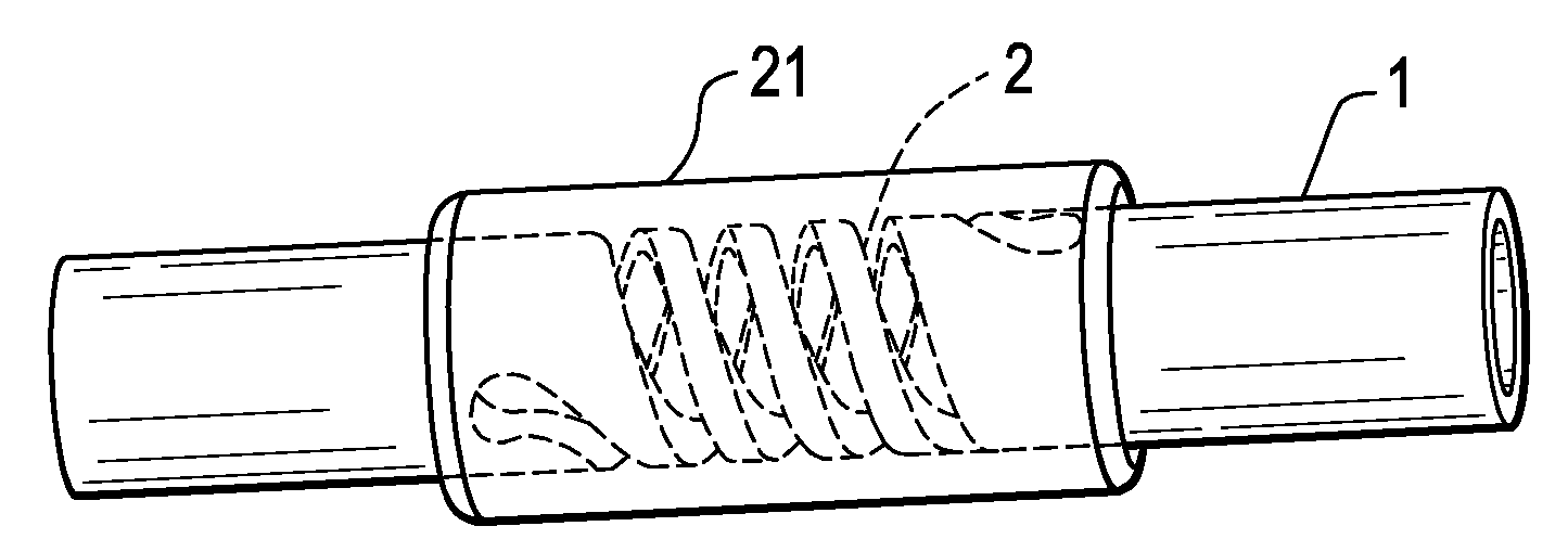
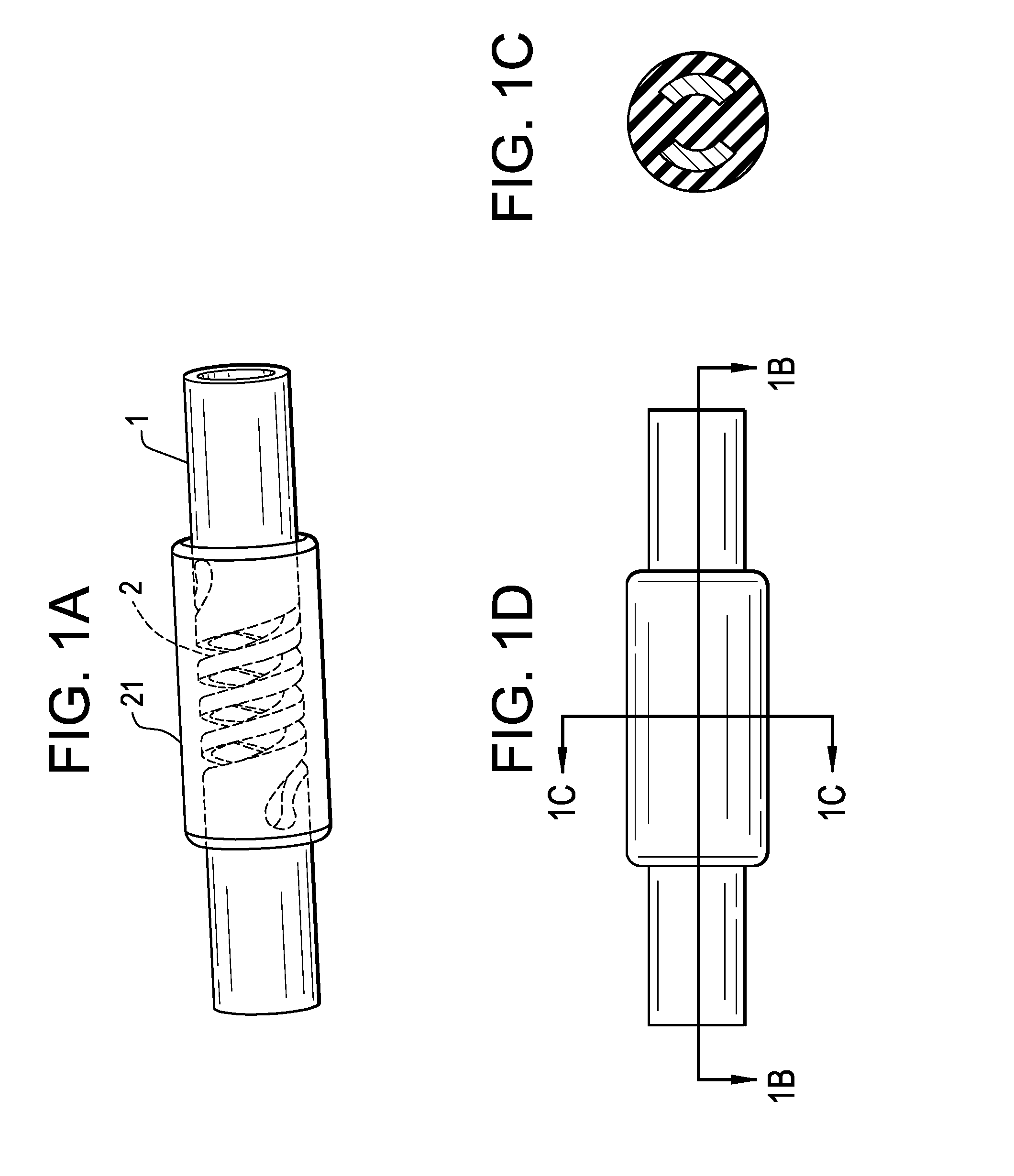
[0032]In regards to geometry, the core stiffness could be changed by changing its cross-section. In addition, an additional (preferably metallic) stiff core can be placed in the center of the elastomeric core to increase the rod stiffness in bending and shear loading. This rod can be connected to the two caps to act as an elongation limiter. Now referring to FIG. 2, there is provided the present invention, which is a flexible rod for use in spinal stabilization, the rod comprising:[0033]a) a tube 21 having a throughbore 23, a first end portion 25, a second end portion 27, an intermediate portion 29 therebetween, wherein the intermediate portion comprises a helical slit 31 extending from an outer surface 33 of the tube to an inner surface 35 of the tube, the slit defining a gap 37 between the outer surface of the tube and the inner surface of the tube, and[0034]b) an elastomeric core 39 extending throughout the throughbore and gap of the tube and forming a cap 40 upon each end portio...
third embodiment
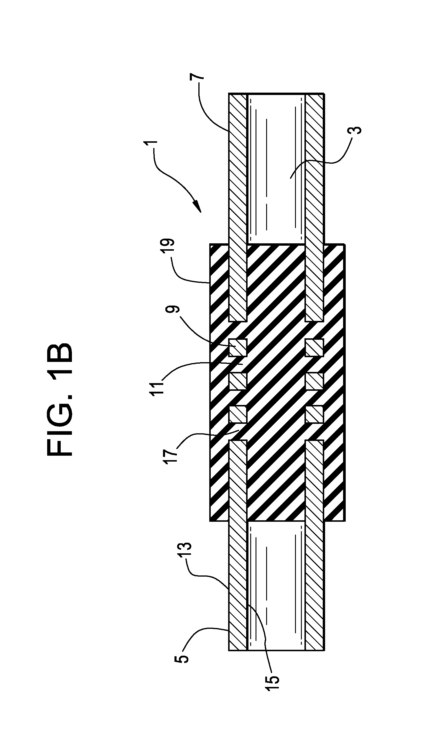
[0037]Now referring to FIG. 3, there is provided the present invention, which is a flexible rod for use in spinal stabilization, the rod comprising:[0038]a) a tube 41 having a throughbore 43, a first end portion 45, a second end portion 47, an intermediate portion 49 therebetween, wherein the intermediate portion comprises a helical slit 51 extending from an outer surface 53 of the tube to an inner surface 55 of the tube, the slit defining a gap 57 between the outer surface of the tube and the inner surface of the tube,[0039]b) an elastomeric core 59 provided within the throughbore of the tube, and[0040]c) an elastomeric jacket 60 provided upon the outer surface of the tube, the jacket covering at least the helical slit,
wherein the gap of the tube is free of elastomer.
[0041]In a fourth embodiment of the present invention, an elastomeric core could be injected into the helical tube component taking care to keep the gaps in the coils free from the elastomer. Holes traversing the thick...
fourth embodiment
[0044]Now referring to FIG. 4, there is provided the present invention, which is a flexible rod for use in spinal stabilization, the rod comprising:[0045]a) a tube 61 having a throughbore 63, a first end portion 65, a second end portion 67, an intermediate portion 69 therebetween, wherein the intermediate portion comprises a helical slit 71 extending from an outer surface 73 of the tube to an inner surface 75 of the tube, the slit defining a gap 77 between the outer surface of the tube and the inner surface of the tube, each end portion having a plurality of holes 78 between the inner and outer surfaces,[0046]b) an elastomeric core 79 provided within the throughbore of the tube and extending into the holes to lock the elastomer,
wherein the gap and outer surface of the tube are free of elastomer.
[0047]As a fifth embodiment, instead of using voids to attach the elastomer to the tube (as in the fourth embodiment), the elastomeric core could have grooves at either end which mate with ta...
PUM
 Abstract
Description
Claims
Application Information